Introduction
I would like to describe how memory paging works. So far, I have played with x86 paging, x86_64, ARM, and avr32 paging. All 4 architectures are different but they share some fundamental concepts that I will try to describe here. There are many ways to implement a paging mechanism, but I am only sticking to the basics here. In my opinion, this article is a good place to start if you want to understand the basics of paging before moving to the technical details and advanced algorithms.
Mathematics of pages
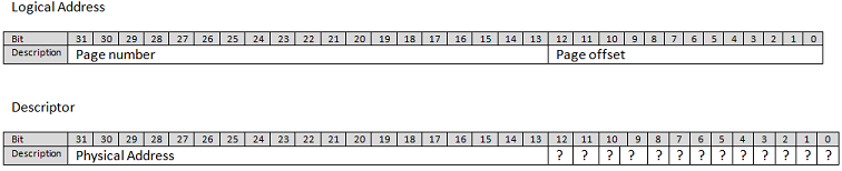
When an instruction attempts to access a memory location, let`s say at address 0x00002345, the MMU will treat that as a logical address. It will separate the address into a page number and an offset. If using a paging system with a 4k page granularity, pages will be 4k each. By taking the address and dividing it by 4096, you get a quotient of 0x02 and a remainder of 0x345, so the mmu would determine that the address points to page #2 at offset 0x345 within the page. The fact that page sizes are always powers of 2 is very convenient because instead of doing a division by 4096, you can simply extract the right-most 12 bits as the offset and all upper bits as the page number. So page_number = address>>12. offset = address&0xFFF.
Note that when using a logical address, you don't need to think about the page number and offset. Using address 0x00002345 will yield page 0x2, and offset 0x345, and if you go 4k above that, the address would be 0x00003345, so page 0x3 and offset 0x345. This is all done naturally.
Page tables
Page tables are tables of descriptors residing in memory.
Each descriptor is, for example, 8bytes long, or 64bit. Each descriptor are in order of pages. Descriptor 0
contains information about page 0 (0..4095), Descriptor 1: page 1 (4096..8191),
Descriptor N: Page N (N*4096..(N+1)*4096-1). A descriptor is a mapping to physical memory, it contains
a physical address. So let's say you need to access logical address 0x0000000000003DEF, the MMU will determine
that you want to access page 3, offset 0xDEF. The 3rd descriptor could hold the value 0x0123456789ABC000.
So that means that the MMU will map the logical address 0x0000000000003DEF tp physical address
0x0123456789ABC000 + offset 0xDEF, so 0x0123456789ABCDEF. See we have just transposed the offset over the
physical address? That is no coincidence. It is because the addresses in the descriptors will always be
a multiple of 4096, since pages can only start on a 4k boundary (for 4k pages that is). Therefore,
the 12 lower bits of the descriptor will always be zero. For that reason, those bits are always reused to
contain other information about the page such as permissions etc... But that is out of the scope of this article.
Basically, what this all means is that the mapping is like this:
PhysicalAddress = (PageTable[LogicalAddress>>12] & ~0xFFF) | (LogicalAddress&0xFFF).
The mapping is done transparently by the CPU!
So far, paging is cool, but here is why it is powerfull: There can be many page tables in memory and at any moment, the MMU can be instructed to use another table to change the mapping. Usually, in an operating system, you want to use 1 page table per process. Let's say you write an operating system, and to make things simple, you want the heap space of each process to begin at 0xBEEF1000. That is easy enough with paging because you just create a page table for each of the processes and out an address in page number 0xBEEF1. Obviously, you don't want each process to overwrite the data of the other processes, so the page 0xBEEF1 in each different page tables would point to a different physical location.
Note that if you only have 1g of RAM, the last accessible memory location would be 0x0FFFFFFF. But there is no limit to the logical addresses (other than the architecture size, 32bits or 64bit) as long as they map to a valid physical location (that is, under 0x40000000 if you have 1gig).
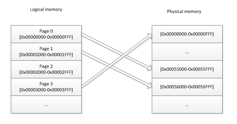
Since each process can have a full page table to themselves, it means that, as far as they know, they have a full 4gig of RAM (in the case of 32bit architecture) that they can access. so let's say that you have 4 process and 4 gig of RAM.
- Process 1 maps the first gig of logical addresses to the 1st gig of physical addreses.
- Process 2 maps the first gig of logical addresses to the 2nd gig of physical addreses.
- Process 3 maps the first gig of logical addresses to the 3rd gig of physical addreses.
- Process 4 maps the first gig of logical addresses to the 4th gig of physical addreses.
If process 1 needs more memory, it sees that only the 1st gig of memory is used (because it only deals with logical addresses and not physical addresses). So it will naively think that there is 3 gig of RAM left. It will ask the kerl to map another gig of ram, but the kernel will say: Wait! there is no more physical memory to which I can map these logical addresses. Well that's not entirely true. This is where swapping comes in.
Page Swapping and Page faults
When the kernel runs out of physical memory so map to logical memory for a process, it will re-use a physical location. There are many ways of determining which physical location to use, but for simplicity, let's assume that this would be done randomly. As per our example above, all 4 process uses all the memory. Process1 requests the kernel to map some physical memory to logical address 0x40000000. The kernel has no more physical memory to hand out so it will pick a random location and will choose physical address 0x80000000 for example. This address is mapped to Page 0 of Process 3 already. So the kernel will modify the page descriptor 0 in page table of process 3 and mark it as invalid. Remember the low 12bits that are unused in the descriptor and I said there would be used for information about the descriptor? Well the "invalid" bit is one of those 12 bits. The kernel will then take the full 4k residing at that physical location and store it on the hard drive, in a swap partition (or file). It will then map the newly requested logical space for process 0 to that physical location. At this point, we have 2 process that have 2 different pages that points to the same pysical location. Only one of those process has the page marked as being valid in its descriptor.
When execution resumes on process2, it could attempt to access page 0 of its logical space. When it does, the MMU will see that the page is marked as invalid and will trigger a Page Fault exception. The kernel will then handle the page fault exception. It will swap the 4k in memory with the one that was previously stored on the hard drive. mark the page in fault as valid and mark the other one as invalid. And that is how swapping works.
Fragmentation
Another use of paging is for memory fragmentation. Let's say that you have 2 process. and only 16K of memory, so 4 pages of 4k. Process 1 is uing 2 4k buffers and has a mapping like this:
- Page0 = 0x0000
- Page1 = 0x2000
- Page2 = unused
- Page3 = unused
it means that Process 1 is using 8k of RAM. There is only 8K of RAM left. Process2 comes in and wants to create a buffer of 8K. Obviously, it expects that buffer to be contiguous memory. But that would be impossbile since there are only 2 4k chunks left and they are not contiguous. Pagin will solve that. Process2 will have a mappint like this:
- Page0 = 0x1000
- Page1 = 0x3000
- Page2 = unused
- Page3 = unused
When process2 will access logical address 0x0000..0x0FFF, it will be transparently redirected in 0x1000..0x1FFF and then when it continues to 0x1000...0x1FFF, it will be redirected in 0x3000..0x3FFF. So the logical memory IS contiguous. This concept makes it very easy to avoid memory fragmentation as we allocate/deallocate memory dynamically.
Translation Lookaside Buffer (TLB)
When an access to memory is requested, the CPU needs to translate the virtual address to physical address. Like I mentionned above, this is done by walking through the page tables. This process adds a significant ammount of time to the memory access because the CPU need to make one or several memory access just to decode the address. So we are talking about more than 100% overhead here. To reduce the impact of this process, most CPU (if not all) implement what is called the Translation Lookaside Buffer, or TLB. When a virtual address is translated, the result is stored in the TLB. So when the next memory access is requested, the CPU will start by looking in the TLB. If a match is found, then it doesn't need to look into the page tables. The TLB is inside the CPU, so accesses to it is very fast. But the TLB has a limited size. When a new virtual address is translated, and the result cannot be stored in the TLB, the CPU will choose a "victim" entry (the word victim is actually a word that some official documentation use) and delete that entry to replace it with the new one. The algorithm for choosing the victim depends on the CPU implementation, but would mostly be a "least recently used" type of algorithm. The TLB works kind of like a DNS cache but without TTL.
When a context switch occurs, the new running process might want to use a different page table for its own translation. That is actually one of the many benefits of using a virtual memory system: so that each process can have their own translation tables. The OS would then instruct the CPU to use another table by giving it the base address of the new table. But the TLB still holds some translation that might not match the new table. We call those entries "stale entries". So when updating the Page Table Base Address, we must also flush the TLB to remove all stale entries. But flushing the TLB could add a significant ammount of processing. And what if the new process only needs 1 translation, and then we context-switch back the the old process. There could be enough place in the TLB to store all the needed translation for both process. So flushing the TLB is very inneficient in that case. That is why most CPUs will implement the concept of an Address Space ID (ASID). On a context switch, ou would update a special register in the CPU to tell it the ID of the currently running process (that would be the ASID). When the CPU adds an entry in the TLB, it will add a "tag" to the entry, that tag would be the ASID. When a TLB lookup is performed by the CPU, any entries tagged with an ASID that does not match the current ASID will be disregarded. So it would be possible to have two identical translations but with different ASID. This illiminate the need to flush the TLB on every context switch because stale entries will be tagged with a different ASID anyway. When the TLB becomes full, the victims will preferably be entries for other ASID than the current one.
Some translations might need to be performed very often. Let's take, for example, the page containing the code for interrupt handlers. That page needs to be accessed very fast, and we would want it to stay in the TLB all the time. Most CPUs offer the possibility to mark some TLB entries as "permanent" or "locked". These entries will never be chosen as victims if the TLB becomes full.
I've seen architectures, such as the AVR32, that doesn't do automatic TLB bookeeping. When a TLB miss occurs, they triger an exception and it is the duty of the OS to fetch and decode the page descriptor and load it in the TLB.
Addressing Space Limitation
Some people may wonder, if my CPU is a 32bit CPU, why can't I use 4gig of RAM?. This is because a 32bit CPU can only use a 32bit integer as the address of a memory location. So it could address 4 gig of RAM theoritically. But you might have a video card in your computer that has 1gig of RAM on it. That 1gig must be accessible by the CPU. So if you have 4 gig of RAM and 1gig in the video card, it means that your CPU would need to access a total of 5gig of ram, but that is impossible. You video card's RAM will be assigned a physical range of addresse. The 32bit adressing really just defines an addressing space. This is kinda like if you were living on a very long street but there is a rule in your neighbourhood that prevents you from using more than 2 digits on on the address plate of your house. Even though about 1000 houses could be built on that street, after the 100th house, the next ones couldn't be assigned a house number because the addressing space was all used up. In my example, I talk about a video card, but there are many other peripherals that uses addresses from the addressing space.
Then you might wonder: how come I have a 32bit CPU and I can access my full 4gig on linux or windows 7? This is because newer (they are actually old at the moment) CPUs have a 36bit addressing mode even though the CPU is 32bit. But the OS must make use of that. WindowsXP did not use the 36bit addressing mode even if the CPU offered it. That is why it was impossible to use your whole RAM on windowsXP