NETWORKING IN MY OS
2016-04-14

Designing my OS
When I design and code my operating system, I usually document what I do in a couple markdown files. I thought maybe some people would find it usefull to see them so I am posting one here. This one is about the networking architecture of my OS. Note that this is really the product of my imagination so it might not be (or should I say it definitely isn't) the best way of doing things. It's just the way I imagined it and it actually works.
Of course, I can't pretend this is only the product of my imagination. I did get a lot of inspiration from many sources online. But I tend to stay away (as much as I can) from the linux source code. Since I think Linux is such a great implementation, it would be too easy to assimilate a lot of its concepts while looking at it. Because once you look at it, you realize that what you're looking at is probably the best way to do things. Take sockets for example. Once you are used to using sockets with open/send/recv/close, how else would you do it? So I ended up doing that because it's what I know. But I have no idea how linux works behind the socket implementation, so I tried to design it the way I think it works. I'm not looking at conceiving the best thing, I'm looking at picking my brain and create something that works the way I imagined it. Maybe like art instead of science.
There are flaws and still open questions but it does work. I don't have any code to post here because I am thinking on either posting the whole code on my website or on github. I have to sort that out.
Network card drivers
The netcard abstration layer is contained in netcard.c.
When the OS boots, net_init() is called. This function
iterates through the PCI bus's devices to find all devices
that match one of the OS's netcard drivers. For each netcard
found, a struct NetworkCard is instanciated. The structure
contains several function pointers that are initialized with
the matching driver's functions. For example, NetworkCard::receive
would be set to &rtl8139_receive if the netcard was a rtl8139.
Each of these NetworkCard instances will be refered to as the
"netcard implementation"
Only the rtl8139 driver is implemented right now. You can view the source code
I have posted a while ago in Realtek 8139 network card driver
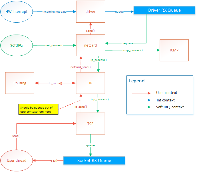
When a netcard IRQ occurs, a softIRQ is scheduled. (I know, softIRQ is a linux concept. But I actually
thought about it before knowing it existed in linux. I didn't have a name for it so I found that Linux
had a great name so I stole it. But it doesn't really work like linux's softIRQ. Linux has a way better
way of doing it than my OS). When the softIRQ handler is invoked, it calls net_process(). net_process() iterates through all netcard that was discovered during boot.
It then checks if data is available and forwards the the data
up to the TCP/IP stack if the data is an IP packet, or to the
ICMP stack if the packet is of the ICMP type.
TCP/IP stack
Receiving data
The ICMP handler responds immediately to ping requests. Therefore
the ICMP response is sent from the softIRQ thread. This allows
consistent RTT. The IP handler forwards the message to the TCP or
UDP handlers. The UDP handler is not implemented yet. The TCP
handler forwards segments to active sockets by finding the socket
listening to the port and ip of the message. This is done by by
finding the socket instance within a hash list. The message is added
in the socket's queue. The user thread is then responsible for
dequeuing those messages.
Sending data
The netcard abstraction's net_send() function locks
the netcard implementation's send spinlock. This way, only
one thread can send to one given netcard at the same time.
net_send() takes an interface index as destination parameter.
ip_send takes an ip address as destination parameter. ip_send
invokes ip_routing_route() to determine on what netcard
to send the message based the destination address.
net_send() will send 1 frame of maximum MTU size. It returns 0 if sending failed
or size of frame if sending suceeded. Frames are guaranteed to be sent in full or
not at all but never partly.
ip_send() will send a packet of maximum 65536 bytes. It will do ip fragmentation
in order to send frames of appropriate size.
tcp_send() will send 1 segment of maximum 64k. This means that the underlying
ip_send() can end up calling net_send several times.
Problem
There is actually a design flaw with tcp_send right now. Sending data on a socket
will end up in netcard_send being called from the user thread. The call is thus blocking.
Also, If net_send() returns 0, because of HW buffer overflow, then ip_send will return the
number of bytes sent. But tcp_send should not attempt to send the rest of the data
because the IP protocol expects the rest of the packet.
IP routing
IP routing is a whole subject itself. There are many algorithms and many ways to do this. It's actually the center of a very big industry.
Basically, when a packet needs to be sent out, we know destination IP to which we want to send. The OS needs to know out of with netcard
(if there are more than one) to send the packet and it also needs to know the source IP address to put in the packet. Normally, there
would be one IP per netcard. Linux allows you to setup multiple IP for one physical netcard, so this would be done by creating virtual netcards.
So the rule would still hold: 1 IP per netcard. My OS does not support virtual netcards, so only one IP per physical netcards.
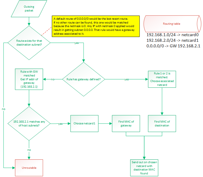
This is all done with a routing table. By default, the routing table will consist of an entry for each IP configured IP for the host.
Those route would be something like "anything within my own LAN must be forwarded out on my netcard". So if netcard0 has IP 192.168.1.88/24
and netcard1 has IP 192.168.2.25/24 then the routes would be:
- 192.168.1.0/24 -> netcard with IP 192.168.1.88 (netcard0)
- 192.168.2.0/24 -> netcard with IP 192.168.2.25 (netcard1)
A route can either say:
- if destination IP matches my subnet, then route out of interface X
- if destination IP matches my subnet, then route out to GW with IP address X
To match a rule, the rule's netmask is applied to the destination IP and the rule's IP. These masked IPs are subnets.
If both subnets match, then the rule matches. A rule of 0.0.0.0/0 would be a default route and would guarantee to always match.
It would be the last resort route.
Usually, routing out of an interface is done when we expect a device connected on that interface (through a switch probably)
to be able to recognize that destination IP. When routing to a GW IP, it is because we expect a specific device to know where
to find that destination IP. This would be a router. A default route would be configured like that. If an outgoing packet's destination
IP address matches the default route, it means it couldn't match any of the other routes. So we want to send that packet
to a gateway. We expect the gateway to be able to route the packet because our own routing table can't.
So the destination subnet is verified in order to find a route for that subnet. The subnet is the IP address logically AND'ed with
the netmask.
Then a route for the default gateway must be added. This will tell: "Anything not matched in the LAN IPs must be sent to this IP".
So something like: 0.0.0.0/24 -> 192.168.2.1. So if something needs to be sent to 192.168.5.6 then that route would be matched. The OS
would then compare the subnet (using the netmask) of that gateway with the IPs configured on the host. It would find that this IP
(of the gateway) is on the same LAN than 192.168.2.25 so netcard1 will be chosen as the outgoing netcard and the destination MAC
address of the gateway will be used. So it is clear that using a gateway that reside on a subnet that doesn't match any of the host's
IPs would be an invalid
configuration.
Frame forwarding
At the layer 2, devices don't know about IP addresses. They only know about MAC addresses. Only devices connected together on the same
layer 2 network (physically connected with switches) can talk to each other. When a packet is ready to be sent out, its MAC address might
not be known yet. The OS will discover it by sending an ARP request: "who has IP 192.168.2.1?". Then, that device will answer
"Me, and my MAC is xx:xx:xx:xx:xx:xx". So that destination MAC address will be used. When sending a packet to an external network, that is
behind a router, such as the example of 192.168.5.6 earlier, the destination MAC of the gateway will be used. So if we send a packet to a
device (by selecting its MAC as the destination) but the destination IP does not match that device's IP, it means we are expecting that
device to be able to do layer 3 routing. Such a device would generally be a router. But it could also be any workstation on the LAN.
Those workstations could be able to route. Linux does it.
Blocking operations
All socket operations such as connect, accept, send, receive and close are
non-blocking. This implies that the lower-level layer operations are non-blocking
also. There are some exceptions to this, but only because there are design flaws
that need to be addressed.
Problem
Upon connecting a socket, ARP discovery and DNS resolution might need to be
performed. DNS resolution will be left to the user to do. connect() will require an
IP address. Upon connect, the socket will be placed in "arp discovery" state. The MAC
address will be fetched from the cache or a discovery will be sent. Upon receiving an
ARP reply, or any other ARP cache entry addition, the stack will search through the
socket list for sockets that are waiting for that entry. The connection will then be
resumed. Once the an ARP entry is found for a socket, it will be saved in the socket
and reused for all remaining transmission.
Locking
At any time, only two threads can access the tcp/ip stack: The softIRQ thread,
for processing incomming frames, and the owner of the socket. If multiple
threads want to share socket usage, they will have to implement their own
locking mechanism. The tcp/ip stack will only guarantee thread safety between
the two threads mentioned above. Sockets should be used by one thread only in
a user application. Two different sockets can be used by two different threads
at the same time though.
net_send() locking
net_send() is used by the softIRQ context and user threads. Since
the softIRQ context has high priority, it means that if a thead
is preempted while it was holding the netcard's send spinlock, and
then the softIRQ attempts to request the lock, a deadlock might occur.
On uni-CPU systems, a deadlock would occur because the softIRQ will
never give CPU time to other threads until it has completed its work.
This could also happen on systems where the number of netcard is
greater than or equal to the number of CPUs.
To solve this problem, the spinlock will disable interrupts.
- Spinlock will prevent another CPU from accessing the send function
- The thread would not be preempted on the local CPU so there is no chances that a softIRQ would deadlock (since softIRQ are prioritized over that thread, it could continue to run and never give time to the thread to release the lock).
- On a single-CPU system, the interrupt cleared and spinlock would be redundant but would not cause a problem
Socket locking
No locking is currently done at the socket level. The following is a list
of problems that would arise, and the associated solution
Problem 1
- Make sure a thread does not delete its socket while softIRQ is using it.
- A thread might want to get the seqnumber while the softirq is modifying it.
- A thread might read in the receive queue while softIRQ is writing in it
Solution
??????
Problem 2
Make sure that only one consumer at a time can append/remove from the socket list.
Solution
The hash list is thread safe so it should already be handled correctly.
But more tests need to be done because there is a little more to it than
just accessing the hash list.
Problem 3
Socket backlog list might get accessed by softIRQ and owning thread
Solution
??????
Accepting incomming connections
A socket is created using create_socket(). Then the socket is placed in listening
mode with listen(). listen() will set the source ip/port of the socket as per
parameters of the function and destination ip/port to 0. A backlog buffer is created
with size=(sizeof(socket*)*backlogCount).
When a segment is processed by tcp_process (in softirq context), a socket will try
to be matched. If no socket is found then tcp_process() will try to find a listening
socket that uses the same source ip/port (matching the received segment's destination
fields) and with destination ip/port set to 0. if a socket is found, then we know
that this segment is for an incomming connection.
The listening socket will only process SYN segments and will ignore any other
segments. When processing a SYN segment, it will create a new socket with the same
source ip/port and with destination ip/port matching the source of the incomming
segment. The state will be set to CONNECTING. The new pending socket will be saved
in the listening socket's backlog. The new socket will stay in the backlog until it
gets picked up by accept(). accept() will then move the socket to the main list. The
socket created in the backlog is only temporary. accept() will create a new socket
instance based on that socket so that the new instance will reside in the accepting
process's heap.
When the accept function is called, it will go through the backlog of the listening
socket and will finish creating the socket. It will clone the socket and create the
receive buffer and send the syn/ack. The socket will stay in "CONNECTING" state until
it receives the ack of the syn/ack accept will move the socket from the backlog to
the main list.
Other articles about my OS
Process Context ID and the TLB
Thread management in my hobby OS
Enabling Multi-Processors in my hobby OS
Block caching and writeback
Memory Paging
Stack frame and the red zone (x86_64)
AVX/SSE and context switching
Realtek 8139 network card driver
ESP8266 BASED IRRIGATION CONTROLLER
2016-04-08
Introduction
In the past couple of months, I've taken interest in the popular ESP8266 wifi enable uC.
I've also wanted for a long time to start designing PCBs, so I decided to mix both interests
and build an irrigation controller. I am no expert in PCB design nor any electronics for that matter.
I'm a software guy. So this whole PCB design is done in a very amateur way and some of the experts
out there might find many flaws in my design. But the important thing is that it does work
as expected and most of all: I had a lot of fun and learned a lot of things while doing this.
That project may look like a failure to some, but it is definitely a victory for me since I ended
up learning things. And next time, I'll learn even more until I get good at it. That's the process
I went through to learn about software design. I have to fail once before taking on the theory.
Overview
An irrigation controller is a pretty simple device. It's just a couple of relays,
a microcontroller and a power supply. For my project, I decided to use 4 relays (to control 4 valves).
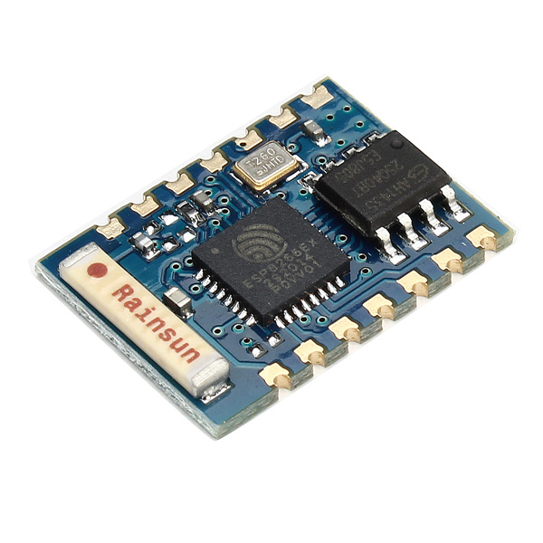
The uC I chose is a esp8266, more specifically, the ESP-03 board. This brings wifi capabilities
to my project. So the esp8266 connects to my network and with a multicast message, it advertises
its presence. My New Home Automation system
then picks it up and connects to it. From that point, it can control all 4 valves.
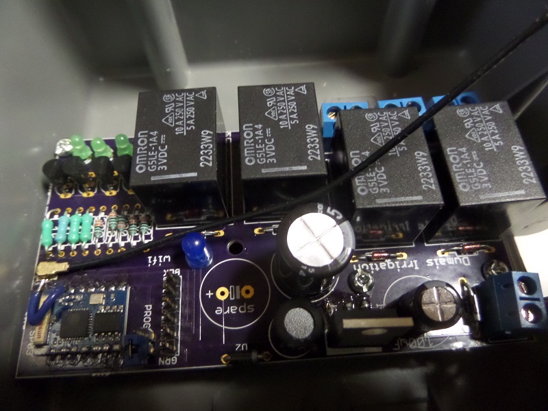
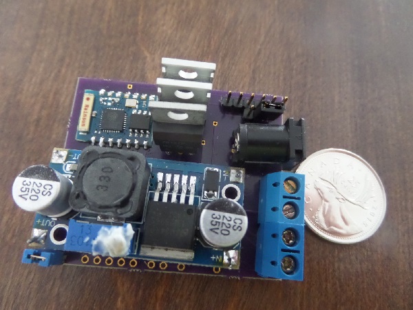
Part list
- My custom built PCB
- esp-03
- 4 G5LE-1A4 relays
- 1 LM2596
- capacitors (see diagram for values)
- resistors (see diagram for values)
- diodes (see diagram for values)
- uf.l SMD connector
- 2.4ghz adhesive antenna
- 4 MPS2907A transistors (PNP)
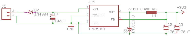
Power supply
The ESP8266 needs a 3.3 VDC input and my valves need 24VAC. So I decided to supply
my board with 24VAC, supply the valves (through the relays) directly and convert to 3.3vdc
before the ESP8266 input. I had very limited experience in designing a power supply before
this project. I still do. But I figured that using a diode and a capacitor, I could easily convert
VAC to VDC. I then used a switched regulator to convert the high VDC down to 3.3v. I used the LM2596T
regulator because I already had some pre-built power supplies that had that on it and found that
they were working pretty well. The choice of capacitor to use was confusing. Looking online, I found
many people using different values than what the datasheet suggests. So I experimented with a breadboard
until I found a combination that worked (I know....). So bascially: 24VAC gets converted to something like
33VDC after going through 1 diode and a capacitor to smooth it out. Then Through a LM2596 to step down to 3.3V.
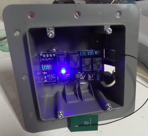
Antenna
I wasn't expecting to use an external antenna at first. But when trying my board for the first time,
I saw that it couldn't connect to wifi. When I designed the PCB, I added a trace to a SMD uf.l connector.
But at that time, I had no connector nor any antenna on hand. So I was wondering if that trace could be the problem.
So I cut it. But it still wasn't working. So I finally bought a connector and an antenna, soldered a wire on the
board because the trace had been cut. And then everything worked out great. So yeah, you need an external antenna. The
small ceramic antenna on the esp-03 won't do the job. Possibly because I put it too close to the power supply on my board?
Or because I have no ground plane? I have no idea, that's something I'm gonna have to investigate.
Transistors
The choice of PNP transistors was because the ESP8266 GPIO are set high on boot. So I wanted my relays
to stay opened during that time. I keep all GPIOs high when valves must be shut off, and pull the GPIO down
when a valve needs to be opened. I did a lot of searching about where to put the load (my relay) in the circuit.
Do I put it after the collector of before the emitter? Apperently it's better to put it after the collector. I still
don't understand why though. So I still have some reading to do. But it works.
Firmware
I've already talked about the basics of the ESP8266 in my
Led strip controller using ESP8266. article.
It is using my custom made protocole "DWN protocol" to speak with my home automation software.
So after my home automation software is connected to the irrigation controller, it sends 2-bytes commands
to activate a valve or to turn it off. The firmware takes care of a couple of things like:
- Hard limit of 30 minutes "on" time for every valve. In case you forget to shut it off. If longer
period is needed, then the controlling software will need to take care of it.
- Only 1 valve at a time can be opened. If the controlling software opens a valve, the irrigation controller
will shut off any other opened valves.
- No valve sequence support. For example: V1 on for 10min, then V3 for 5min and then V2 for 1min. This needs
to be done by the controlling software.
The sources:
Flaws
So far the biggest flaw I found is that I mixed up the RX/TX pins of the FTDI header. In eagleCAD, the part I was using for
the header had to have its RX connected to the uC's RX pin. I didn't know that, I thought I had to reverse them. If I had looked
at the FTDI pinout, I would have noticed it. Lesson learned. But it's not a big deal, I made an adapter that reverses both pins.
Also, like I said earlier, the wifi doesn't work without an external antenna. No big deal, I can use an external antenna.
But I added that SMD footprint like 5 min before sending to the fab. I'm pretty glad I did that. The lesson learned here:
anticipate for errors: put extra stuff in case you need it. That's obviously not good thinking for production but for a
hobbyist like me, it's a good thing to do. Noticed the "spare" capacitor foot print on the board? hehehe.
Questions?
I've seen a lot of amateur projects like mine on sites like Hackaday and a lot of people
always make the same comments so I figured I'd answer those questions immediately.
- Why did you do it this way instead of that way? Because I felt like doing it that way.
- Why not use this and that instead? Because that's not what I felt like playing with.
- Isn't this a fire hazard? I don't know! Is it?!?!?! Please tell me at youjustbuiltadeathtrapyoulunatic@dumaisnet.ca
- Why not use an Insteon EZFlora? I did. But I wanted to build an irrigation controller. So now my EZFlora is useless
LED STRIP CONTROLLER USING ESP8266.
2016-03-02
I recently installed an RGB led string under my kitchen cabinet. I wanted to way to control it using any web browser on a cell phone, tablet or
desktop computer. There are many ways I could have achieved this but this time, I wanted to do it all by myself and design
my first PCB. This is how I did it.
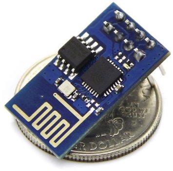
ESP8266
The ESP8266 is small cheap wifi microcontroller. It is a 32bit microcontroller with and external 1024kb or flash memory.
There are tons of information out there about this chip so I won't dig too much into the basics.
When I discovered this board, I realized the potential it could bring to my home automation projects. I can now have multiple
devices that talk to my central software (New Home Automation system) wirelessly.
Firmwares
The ESP8266 usually comes with a pre-loaded "AT" firmware. If it isn't, you can download it for free
and upload it, using an FTDI cable, to your chip. The AT firmware is a simple firmware that lets you
send "AT" style commands, like in the old days with modems, to control the chip. There's an AT command to
connect to an access point, another to start a TCP server, another to send a packet, etc.
A lot of people use the AT firmware. This allows you to connect a another microcontroller to the ESP8266 using the UART pins
and send commands to the device. But you can also write your own firmware and take advantage of the the 1024kb of
flash on the chip. You have a few GPIOs and 2 UARTs. You don't need an external microcontroller.
Environment
To upload a firmware, whether it is the AT firmware or your own, you will need the flash tool.
To build your firmware, you will need a complete toolchain. The esptool can be found at
https://github.com/themadinventor/esptool/. Once you have downloaded the file,
just copy it somewhere like in /usr/bin so that it is in your exec path. To upload a firmware, you must obviously obtain one or build one.
The firmware is separated in a couple of file. If you are uploading the AT firmware, this should work (change /dev/ttyUSB8 for the serial port where your FTDI cable is attached):
esptool.py --port /dev/ttyUSB8 --baud 9600 write_flash 0x00000 boot_v1.1.bin 0x01000 v0.20/user1.bin 0x7c000 esp_init_data_default.bin 0x7e000 blank.bin
Programming
Keep in mind that the chip must be reset while GPIO0 is pulled low in order to enter the bootloader to accept a firmware update. To create your own firmware,
you will need to download the toolchain. The following should get you going:
git clone --recursive https://github.com/pfalcon/esp-open-sdk
make STANDALONE=y
mv xtensa-lx106-elf /opt/
Now add /opt/xtensa-lx106-elf/bin in your PATH. Next, you will need a Makefile. I've created the following:
all: firmware

TTY=/dev/ttyUSB8
SRC = main.c
OBJECTS=$(SRC:.c=.o)
CC = xtensa-lx106-elf-gcc
CFLAGS = -I. -mlongcalls
LDLIBS = -nostdlib -Wl,--start-group -lmain -lnet80211 -lwpa -llwip -lpp -lphy -Wl,--end-group -lgcc
LDFLAGS = -Teagle.app.v6.ld

.c.o:
    $(CC) -c $(CFLAGS) $< -o $@

firmware: $(OBJECTS)
    $(CC) $(LDFLAGS) $(LDLIBS) $(OBJECTS) -o firmware.elf
    esptool.py elf2image firmware.elf

install: firmware
    esptool.py --port $(TTY) --baud 115200 write_flash 0 firmware.elf-0x00000.bin 0x40000 firmware.elf-0x40000.bin

clean:
    rm *.bin
    rm *.elf
    rm *.o
Again, remember to reset the chip with GPIO0 pulled low before invoking 'make install'. Here is a basic source file to build a firmware
#include "ets_sys.h"
#include "gpio.h"

void ICACHE_FLASH_ATTR user_init()
{
    gpio_init();

    PIN_FUNC_SELECT(PERIPHS_IO_MUX_U0TXD_U, FUNC_GPIO5);
    gpio_output_set(BIT5, 0, BIT5, 0);
}
Notice how the entry function is called user_init() instead of main(int argc, char** argv). This is because you are not running your firmware
bare-metal on the board. There is an OS running in there and it will invoke user_init(). This is an event-based system. You cannot make an infinite
loop like you would on another microcontroller. Instead, you let the OS run and hook your app to some events with callback functions. There is a
way to create a timer and give the OS a pointer to your timer callback function. You can also give the OS a function pointer to a message handler
and post messages to your app in order to receive messages in your message handler. If your code takes too much time inside a callback, the OS watchdog
will reset your chip. So you cannot make infinit loops nor complex functions that do massive computations. You have to build your architecture
around a single-threaded event-based system. Kindof like a javascript application.
The SDK, included in the toolchain, is pretty easy to use. For examle, to connect to a wireless access point, all you need to do is:
void ICACHE_FLASH_ATTR init_wifi(char ssid[32], char password[64])
{
    struct station_config station_config;
    wifi_set_opmode(1); // station mode. will connect to AP
    os_memcpy(&station_config.ssid, ssid, 32);
    os_memcpy(&station_config.password, password, 64);
    wifi_station_set_config(&station_config);
    wifi_station_set_auto_connect(true);
    wifi_station_set_reconnect_policy(true);
}

void ICACHE_FLASH_ATTR user_init()
{
    init_wifi("SSID","PASSWORD");
}
If you want to create an infinite loop, as I said previously, you cannot do this within a callback since it will block the
os thread and the watchdog will reset your board. Instead, you need to post your self a message so that the OS will call your function
everytime. For example:
#define TASK_QUEUE_SIZE 64
#define MAIN_LOOP_TASK_PRIORITY 1
os_event_t    main_loop_task_queue[TASK_QUEUE_SIZE];

// handle a message
static void ICACHE_FLASH_ATTR main_loop(os_event_t *events)
{
    // do something with the message
    ...

    // now post a message again to our self, creating an infinit loop
    system_os_post(MAIN_LOOP_TASK_PRIORITY, 0, 0);
}


void ICACHE_FLASH_ATTR user_init()
{
    system_os_task(main_loop, MAIN_LOOP_TASK_PRIORITY, main_loop_task_queue, TASK_QUEUE_SIZE);

    // post a message to ourself
    system_os_post(MAIN_LOOP_TASK_PRIORITY, 0, 0);
}
The Board
I'm not going to show my board diagram, because frankly, I'm a little ashamed of the work I did. This is my first PCB design and I'm still
learning basic electronics. Bascially, I made a PCB with 3 mosfets, a step-down voltage regulator (12V to 3.3V) and a ESP-03 chip.
PWM
The chip supports software PWM for all GPIOs but I never was able to make it work properly. So I ended up writing my own software PWM.
It's pretty straight forward, I just setup a timer and toggle GPIOs according to a duty cycle set by the user application. You can get my source code here:
DWN protocol
For each of my new Wifi devices to talk to my home automation server, I had to invent a new protocol. I could have used MQTT but I felt like
my idea was even more simple. I created what I call the DWN protocol (DHAS Wifi Nodes).
The protocol is very simple. The wifi node broadcasts a JSON message containing its name and unique ID every 5 seconds on a multicast address at port
242. Whenever my home automation server sees such an advertisement, it will detect the source IP address of the broadcasting device and connect to
the device's TCP server listening on port 242. Once the wifi device has a TCP client connected, it continue to send advertisements every 5 seconds and
also sends heartbeats to the connected client. The DWN protocol does not define the format of payloads being exchanged between the home automation server
and the wifi device. The DWN protocol is just a protocol that allows wifi nodes discovery.
Using such a system, my home automation can detect any wifi devices that gets turned on in my house and it will connect to it. Since the devices
broadcast their name (ie: "IRRIGATION_CONTROLLER"), the server loads the appropriate "driver" or "module" for that device and starts communicating
with them. This allows me to have a plug-and-play architecture. If I want to add a second led controller device, I just build one, turn it on and
the home automation server automatically detects it and starts using it.
Future projects
This was my led controller board. I am planning on making a sprinkler controller with a esp-03 board with 4 relays, using the DWM protocol with my
home automation server. I will also make a small device with a ESP-01 board with 2 input GPIOs to monitor my alarm system's relays. I currently monitor
my alarm system's relay with an arduino setup as an ACM device plugged in the USB of my computer. I'd rather go wifi now. I would also like to build
a device that would stay connected in my car. Onces I park my car in the garage, because of the DWN protocol, my home automation server will know
when my car is at home and when it isn't. So as you can see, these esp8266 chips can be used for many things in the home automation world.
OPENVSWITCH ON SLACKWARE
2015-12-23
openvswitch
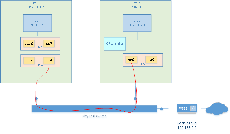
I want to create two VM on two separate hosts (one per host) that reside on the same network. I also
want the VMs to reside in a different network than the host's network. To do this with
openvswitch is really easy.
- Make sure openvswitch and tun/tap are compiled in kernel
- install openvswitch tools
- create bridge on each VMs
- create masquerading rules to share internet connection with VM network
Installing openvswitch
Openvswitch is already part of the kernel. It needs to be enabled when compiling the kernel. Then
the tools need to be installed. On slackware, it was just a matter of ./configure, make, make install.
Creating a bridge with GRE tunnel
To have both VMs communicate with each other, we can build a virtual switch that spans
accross the two hosts. This is done with a bridge containing a GRE tunnel.
Creating a bridge on each VMs is done as follow. Unless noted otherwise, these commands
should be re-executed after every reboot
# create tun/tap adapters
/usr/sbin/tunctl -t tap7

# launch openvswitch server
ovsdb-server --detach --remote=punix:/usr/local/var/run/openvswitch/db.sock --remote=ptcp:6640
ovs-vsctl --no-wait init
ovs-vswitchd --pidfile --log-file --detach

# Creating the bridge. Adding tap interface and GRE tunnel in the bridge
# This is the exception: the following only needs to be done once as it will be persistant
/usr/local/bin/ovs-vsctl add-br br1
/usr/local/bin/ovs-vsctl add-port br1 tap7
/usr/local/bin/ovs-vsctl add-port br1 gre0 -- set interface gre0 type=gre options:remote_ip=**IP_ADDRESS_OF_OTHER_HOST**

# bring the bridge up
/sbin/ifconfig br1 0.0.0.0 promisc up
/sbin/ifconfig tap7 0.0.0.0 promisc up
Then repeat the same on the other host
Now, it is possible to start a VM on each host using their respective TAP7 interface. Each vm is
assigned an IP address in the same subnet but different than the one of the hosts. In my case
I used 192.168.2.2 and 192.168.2.9. Because a GRE interface is present in the bridges, both VM
can communicate with each other now.
Access to the internet
Since the VMs reside on subnet 192.168.2.0 but my internet gateway is at 192.168.1.1, there is no way
for my VMs to communicate with the outside world. So the first thing that needs to be done, is to
assign an ip address to the bridge of one of the host. This will be the gateway. So obviously, only
one is needed. I chose to put it on host2. So the "br1" on host1 still has no ip address assigned to it.
On host2 I did:
ifconfig br1 192.168.2.1/24 up
Then, masquerading needs to be done. This is not absolutely required. But if nat is not used, then
the gateway of the host's network must know about the VM network and have a route to redirect
traffic to the 192.168.2.1 gateway. In my case, I chose to use NAT. The following commands did
the trick:
# Enable forwarding. So that linux will see that
# traffic on br1 that wants to go out on a network known by another
# interface, eth0 in my case, will be forwarded on that interface.
echo 1 > /proc/sys/net/ipv4/ip_forward

# Create IP masquering rules. Assuming that eth0 is the host's interface that can
# communicate with the internet gateway (or is the gateway). Packets destined
# for external traffic will leave out eth0. So make a postrouting rule
# that will masquerade those outgoing packets. This will allow other networks
# to reach the VM network without knowing anything about it.
iptables -t nat -A POSTROUTING -o eth0 -j MASQUERADE
Of course, the default route, within the VMs, should point to 192.168.2.1. At this point
VMs should be able to connect to this website
Additional notes
-
port of type "patch" can be used to "connect a patch cable" between 2 vswitches. This would
be used to connect two vswitches together as long as they reside on the same host. To connect
two vswitches that reside on different hosts, a port of type GRE would be needed.
-
To get additional information on what type of interface can be created (patch, internal, gre, etc.): http://openvswitch.org/ovs-vswitchd.conf.db.5.pdf
-
In the example above, the ovsdb-server was started with --remote=ptcp:6640. This means that it is possible
to control the vswitch from any other host using "ovs-vsctl --db=tcp:192.168.1.2:6640 ". This is great
when a virtual switch spans across several host because all host bridges can be controlled from one single point.
Openflow
The best description of OpenFlow and SDN I found was this:
OpenFlow is a protocol which lets you offload the control plane of all the switches to a central controller and lets a central software define the behavior of the network (also called Software Defined Networks). To me, that description was the one that opened the doors to SDN in a time where all of those terminologies was confusing to me.
Flows
Before going any further, let's first define what a flow is. An open flow switch makes
forwarding/routing decisions based on its flow tables. Each flow represent a "rule" that
must be matched and the action that must be taken if the rule does match. Flows are added
by a separate piece of software to the switch. The switch does not "build" its own flows.
These must be explicitely added to the switch by the switch administrator when first
configuring the switch or dynamically by an SDN controller. If using an SDN controller,
when a frame/packet/segment does not match any flows, it will be sent to the SDN
controller in order to find a flow that matches.
The flows contain a "match" part. It defines fields of frame/packet/segment must be
matched so that the flow applies. If the flow does apply, then the "action" part is used.
Matches can be specify that a flow must match a source MAC address, a destination TCP port,
or any other L2/3/4 fields. Combinations of fields can be matched and wildcards can be used.
The flows also contain an "action" part. Actions are very flexible. I won't detail
all the possible actions here. An action could be to drop the packet, forward the frame,
redirect to another flow table (internal to the switch) etc.
Using openflow with openvswitch
The man page for ovs-ofctl contains a section that details the flow syntax. Here is an example
on how to add a flow that would drop any TCP segment with destination port 80
ovs-ofctl add-flow br0 "table=0, tcp,tp_dst=80, actions=drop"
This one would rewrite any segment going towards TCP port 80 to go to tcp port 25. This is
basically port forwarding. Note that two flows need to be written. Once the server on port 25
sends a reply, it needs to be modified to use port 80 since the client is expecting to be
communicating on port 80.
ovs-ofctl add-flow br0 "table=0, tcp,tp_dst=80,nw_dst=192.168.2.2, actions=mod_tp_dst:25,normal"
ovs-ofctl add-flow br0 "table=0, tcp,tp_src=25,nw_src=192.168.2.2, actions=mod_tp_src:80,normal"
This will add flows to the bridge on the local host. This could be done when configuring the
switch initially. Obviously, more complex (and more useful) flows could be written, but this
is just to get a hang of it.
It could also be useful to have the switch's flow tables be populated dynamically by some other
"brain". Such a brain would be an "opendlow controller". The controller can reside on a separate
host.
I downloaded pox, an openflow controller, on one of my host. I am
running it on a different host than the one that is hosting the vswitch.
vswitch is running on 192.168.1.2 and pox is running on 192.168.1.3
git clone https://github.com/noxrepo/pox
cd pox
./pox.py forwarding.l2_learning
And then, on the vswitch host, I tell the bridge who the controller is
ovs-vsctl set-controller br0 tcp:192.168.1.3:6633
Using "forwarding.l2_learning" with pox creates a very basic flow that makes
the switch act like a normal layer2 switch. You could write other modules
for pox, but that is beyond the scope of this example. At least, now you know
how to have a remote controller generate the flows dynamically. You could download
another software to do it or even write your own.
By the way, using an openflow controller, we could drop the iptables usage from the above section and implement NAT using openflow only.
What this means
I wanted to learn what this was all about and I'm glad I did. I don't fully
understand how this can be very usefull though. I do see the power that this
brings to networking infrastructures. But for me, running a couple of computers
in my basement with a relatively simple setup, it is not that usefull. I can't
list a lot of uses-cases where this would change the world. I'm sure that one
day, I'm going to stumble across a problem and say "Hey! That would be super-easy
to do with openflow" and I'm gonna be glad I learned the basics of it. And now, 2017, I do fully understand the benefits of it because I work for a major SDN solution manufacturer :)