
Preface
This section describes the implementation of my OS at a high level. Not all of it is working right now but this is the basic idea.
Source code
You can download the current code but it is far from being complete.
Download
The big picture
The OS is not meant to be an operating system like linux or windows where user application can run. The purpose is to provide a basic platform to implement different "firmwares". A firmware is a set of application in this context. Depending on what you want your NGW100 to be, you would run a different firmware (set of applications) that would drive the board through services provided by the OS.
The following picture describe what components will be handled by the OS.
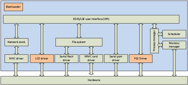
The orange boxes represent modules that will be implemented in the future. The "EDX/LSE" is
an OS specific component, don't try to find info about it in the datasheet. This is described
here
Note how the USB controller, AC97 device, timers and several other devices are not represented in the graphics. This is because the OS won't take care of these devices. Drivers for these devices will be implemented as applications. So if I want to make my NGW100 device act as a USB storage device, I would have to write an application that implements the USB Mass Storage device protocol and use the file system module of the OS through the API. So building a router with my NGW100 would be a matter of developping applications that would run cooperatively like a serial shell app, packet-routing app, web-server app, usb mass storage app, etc.
Virtual file system
The OS will locate files using the following path structure: /0/dir/file. "/0" is the storage device number and the "/dir/file" is the path of a file on that storage device. The following storage devices will be recognized:
| Number | Device |
|---|---|
| 0 | Onboard Dataflash |
| 1 | SD card |
Booting
Booting is currently done with u-boot as I don't have a JTAG tool yet. Eventually, I would like to have it boot on its own. Since u-boot initializes stuff for me, I will be own my own when I take the step.
With u-boot, I am downloading the firmware trough a tftp server and I save the image in the parrallel flash at address 0x00100000. I then execute the code from address 0x80100000 (remember, 80000000 is mapped to 0x00000000). Executing from that address makes the code run in priviledged mode.
After the kernel will start running and all initialization is done, it will look in the dataflash for the boot script. This script contains a list of applications (located on dataflash or SD card) that should run at startup and a some other settings.
Boot script
This file will be located at "/0/boot.script". todo: not designed yet
Initialization
The following is a list of things I am doing before attempting entering the idle loop in my OS
- Reset some CPU settings to default. I looked at what u-boot was doing on reset and I do the same.
- Configure the PM to enable PLL and run at 150MHZ.
- Not sure what the SMC is, but I think I have to set it up in order to use ethernet devices
- Initialize the EVBA and clear interrupt mask flag
- Initialize SDRAM
- Initialize the MMU
- Initialize serial port
Memory Management
Overview
Physical memory usage
| Physical memory | Description |
|---|---|
| 0x00000000 - 0x000FFFFF | Reserved (u-boot is in there) in parallel flash |
| 0x00100000 - 0x0010FFFF | Kernel code in parallel flash |
| 0x00110000 - 0x007EFFFF | Parallel flash. reserved by kernel. Unused yet |
| 0x007F0000 - 0x007FFFFF | Reserved by u-boot (parallel flash) |
| 0x00800000 - 0x0FFFFFFF | INVALID |
| 0x10000000 - 0x1000FFFF | Page table(SDRAM) |
| 0x10010000 - 0x11E73FFF | process memory (SDRAM) |
| 0x11E74000 - 0x11F09FFF | graphic memory |
| 0x11F0A000 - 0x11FAFFFF | reserved |
| 0x11FF0000 - 0x11FFFFFF | kernel buffers (SDRAM) |
| 0x12000000 - 0x23FFFFFF | INVALID |
| 0x24000000 - 0x24000FFF | Kernel Stack (SRAM) |
| 0x24001000 - 0x24007FFF | Kernel heap (SRAM) |
| 0x24008000 - 0xFEFFFFFF | INVALID |
| 0xFF000000 - 0xFFFFFFFF | Memory-mapped IO |
Memory mapping viewed by kernel
| Address range | Description | Relation to physical memory |
|---|---|---|
| 0x00000000 - 0x03FFFFFF | INVALID | Page translated but not handled by OS |
| 0x04000000 - 0x04000FFF | Kernel Stack | Page translated to SRAM |
| 0x04001000 - 0x0400107F | Process Table | Page translated to SRAM |
| 0x04001080 - 0x0400108F | USART0 TX buffer | Page translated to SRAM |
| 0x04001090 - 0x0400109F | USART0 RX buffer | Page translated to SRAM |
| 0x040010A0 - 0x040010AF | USART1 TX buffer | Page translated to SRAM |
| 0x040010B0 - 0x040010BF | USART1 RX buffer | Page translated to SRAM |
| 0x040010C0 - 0x040010CF | USART2 TX buffer | Page translated to SRAM |
| 0x040010D0 - 0x040010DF | USART2 RX buffer | Page translated to SRAM |
| 0x040010E0 - 0x040010EF | USART3 TX buffer | Page translated to SRAM |
| 0x040010F0 - 0x040010FF | USART3 RX buffer | Page translated to SRAM |
| 0x04001100 - 0x0400117F | Reserved fo MMC driver | Page translated to SRAM |
| 0x04001180 - 0x04007FFF | Kernel heap | Page translated to SRAM |
| 0x04008000 - 0x7FFFFFFF | INVALID | Page translated but not handled by OS |
| 0x80000000 - 0x800FFFFF | Reserved (u-boot is in there) in parallel flash | Cached, Segment translated to flash |
| 0x80100000 - 0x8010FFFF | Kernel code in parallel flash | Cached, Segment translated to flash |
| 0x80110000 - 0x807EFFFF | Parallel flash. reserved by kernel. Unused yet | Cached, Segment translated to flash |
| 0x807F0000 - 0x807FFFFF | Reserved by u-boot (parallel flash) | Cached, Segment translated to flash |
| 0x80800000 - 0x8FFFFFFF | INVALID | N/A |
| 0x90000000 - 0x9000FFFF | Page table | Cached, Segment translated to SDRAM |
| 0x90010000 - 0x91E73FFF | process memory | Cached, Segment translated to SDRAM |
| 0x91E74000 - 0x91F09FFF | graphic memory | Cached, Segment translated to SDRAM |
| 0x91F0A000 - 0x91FAFFFF | reserved | Cached, Segment translated to SDRAM |
| 0x91FA0000 - 0x91FAFFFF | dataflash temp buffer | Cached, Segment translated to SDRAM |
| 0x91FB0000 - 0x91FBFFFF | mmc temp buffer | Cached, Segment translated to SDRAM |
| 0x91FC0000 - 0x91FC017F | MACB0 rx descriptor table | Cached, Segment translated to SDRAM |
| 0x91FC0180 - 0x91FC01DF | MACB0 tx descriptor table | Cached, Segment translated to SDRAM |
| 0x91FC01E0 - 0x91FC19DF | MACB0 rx buffer | Cached, Segment translated to SDRAM |
| 0x91FC19E0 - 0x91FC31DF | MACB0 tx buffer | Cached, Segment translated to SDRAM |
| 0x91FC31E0 - 0x91FC31E3 | MACB0 current RX entry | Cached, Segment translated to SDRAM |
| 0x91FC31E4 - 0x91FC31E7 | MACB0 current TX entry | Cached, Segment translated to SDRAM |
| 0x91FC31E8 - 0x91FC31FF | MACB0 net config | Cached, Segment translated to SDRAM |
| 0x91FC3200 - 0x91FC337F | MACB1 rx descriptor table | Cached, Segment translated to SDRAM |
| 0x91FC3380 - 0x91FC33DF | MACB1 tx descriptor table | Cached, Segment translated to SDRAM |
| 0x91FC33E0 - 0x91FC4BDF | MACB1 rx buffer | Cached, Segment translated to SDRAM |
| 0x91FC4BE0 - 0x91FC63DF | MACB1 tx buffer | Cached, Segment translated to SDRAM |
| 0x91FC63E0 - 0x91FC63E3 | MACB1 current RX entry | Cached, Segment translated to SDRAM |
| 0x91FC63E4 - 0x91FC63E7 | MACB1 current TX entry | Cached, Segment translated to SDRAM |
| 0x91FC63E8 - 0x91FC63FF | MACB1 net config | Cached, Segment translated to SDRAM |
| 0x91FC6400 - 0x91FC67FF | ARP cache | Cached, Segment translated to SDRAM |
| 0x91FC6800 - 0x91FFFFFF | reserved | Cached, Segment translated to SDRAM |
| 0x92000000 - 0x9FFFFFFF | INVALID | N/A |
| 0xA0000000 - 0xBFFFFFFF | Same as 0x80000000-0x9FFFFFFF | Same as 0x80000000-0x9FFFFFFF but uncached |
| 0xC0000000 - 0xDFFFFFFF | INVALID | Page translated but not handled by OS |
Memory mapping viewed by application process
| Address range | Description |
|---|---|
| 0x00000000 - 0x000000FF | Application stack |
| 0x00000100 - 0x000001FF | supervisor stack |
| 0x00000200 - 0x000002FF | Reserved |
| 0x00000300 - 0x00000343 | Task context |
| 0x00000344 - 0x000003FF | Reserved |
| 0x00000400 - 0x01FFFFFF | User space. Size may differ, depending on allocated space |
| 0x02000000 - 0x7FFFFFFF | INVALID |
| 0x80000000 - 0xFFFFFFFF | Access denied |
Memory mapping viewed by system threads
| Address range | Description |
|---|---|
| 0x00000000 - 0x000000FF | Thread stack |
| 0x00000100 - 0x00000143 | Task context |
| 0x00000144 - 0x01FFFFFF | Reserved |
| 0x02000000 - 0x7FFFFFFF | INVALID |
| 0x80000000 - 0xFFFFFFFF | kernel space |
Paging
The OS will use paging and segmentation at the same time. This means that the first 2gigs of addressing space will be separated in 4k chunks and remapped on the physical space in another way. More information on this can be found in the AVR32 architecture section of this site. Paging allows us to remap the memory in a non-contiguous way.
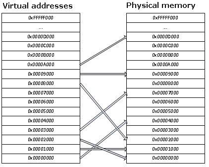
Application processes will use the SDRAM memory. Only the SRAM and SDRAM memories will be paged. The page table will be stored in the sdram and will be 64K in size (8192 pages). 8192 pages will allow us to maintain 4k pages for the reset of the SDRAM and the whole 32K sram. The sram pages will be used as the heap for the kernel and will be protected. The SDRAM pages will be set as private and will be associated with the owning process ASID. In the page table, a page entry will take 64bit in size. The first 32bit is going to be structured like TLBEHI. This 32bit field will allow us to find an entry on the table based on the requested page number and ASID. The last 32bit will be a copy of what should be copied in TLBELO when finding a match for TLBHI. The first 8 entries in the page table will be reserved for the SRAM. The rest of the entries will reflect the physical SDRAM space in the same order. The first 32bits of each entry do not have to be linear though.
Example Page table:
| PageTable 1st 32bits | Page table last 32bits |
|---|---|
| VPN=0x24000 | PFN=SRAMBlock0 |
| VPN=0x24001 | PFN=SRAMBlock1 |
| VPN=0x24002 | PFN=SRAMBlock2 |
| VPN=0x24003 | PFN=SRAMBlock3 |
| VPN=0x24004 | PFN=SRAMBlock4 |
| VPN=0x24005 | PFN=SRAMBlock5 |
| VPN=0x24006 | PFN=SRAMBlock6 |
| VPN=0x24007 | PFN=SRAMBlock7 |
| VPN=0, ASID=1 | PFN=SDRAMBlock0 |
| VPN=0, ASID=2 | PFN=SDRAMBlock1 |
| VPN=89, ASID=1 | PFN=SDRAMBlock2 |
| VPN=9, ASID=1 | PFN=SDRAMBlock3 |
| ... | ... |
The page table will also be used by the kernel to track available memory. A page with the "v" flag cleared means that this page is not reserved by any application so that 4k of memory is free. When allocating memory to a process, the "v" flag of the reserved pages will be set.
Scheduler
The scheduler will use a timer to switch task. A task switch will occur about 20 times per seconds. In order to switch tasks, the current context must be saved in the application space. The scheduler will perform the following tasks:
- Go through the list of process and find the next one to be switched to in a round-robin fashion.
- Using the stmts instruction, save all registers from ro to r14 to the application space buffer. stmts will save the registers from the application context. We will be executing from INT3 so registers r8 to r14 will be shadowed, meaning that even if we change them, stmts will pickup the right values that were assigned before entering INT3.
- Save the RSR_INT3 register to the application space. RSR_INT3 contains the system flags before entering INT3. If the interrupt occured between a "cp.w" and a "breq", teh flags need to be preserved.
- Save the RAR_INT3. This register contains the return address that rete is going to use to resume execution of the interrupted code.
- Change the TLBEHI's ASID. Since we are switching context, the pages won't be mapped the same way. From now on, accessing the data in the application space will give us the data from the new application space.
- using ldmts, restore R0-R14.
- restore RSR_INT3
- restore RAR_INT3, so we can use rete to resume the task.
Dataflash
The dataflash is accessed with the SPI bus. Since the dataflash is not a protable device and only the MCU can access it, it is a good opportunity to design my own file system. That memory will contain the boot script.
Dataflash file system
todo: not designed yet