This is a REST engine API that I use for some of my projects. It is very simple to use and has no dependencies.
One of the nicest feature is that it documents the REST interface that you build with the engine. Note that this
is only a REST engine and does not include a web server. You still need to listen on a socket for incomming requests
and feed them to the engine and respond with the engine's output.
Defining your API and documenting it
Let's say you have an application that has a ShoppingCart object and you want to expose some of its functionality through a REST interface.
Defining the API is easy as this:
ShoppingCart *p = new ShoppingCart();
RESTEngine engine;

RESTCallBack *pc1 = new RESTCallBack(p,&ShoppingCart::addToCart,"This lets you add an item to a shopping cart");
pc1->addParam("id","Shopping cart ID");
pc1->addParam("sku","Item SKU");
pc1->addParam("qty","Quantity of that item to add");

RESTCallBack *pc2 = new RESTCallBack(p,&ShoppingCart::removeFromCart,"This lets you remove an item from a shopping cart");
pc2->addParam("id","Shopping cart ID");
pc2->addParam("sku","Item SKU");

engine.addCallBack("/shoppingcart/item","POST",pc1);
engine.addCallBack("/shoppingcart/item","DELETE",pc2);
Note how each resource uri and parameters are documented at creation time.
Invoking and processing query
To invoke a query, you only need to get the URI (after parsing it from a from a HTTP request or whatever other way) and feed it to the engine. Of course,
your API might want to return some data, so this is done by passing an empty JSON document object (JSON interface is part of the project as well. I told you,
there are no external dependencies in this project :) ) and the callbacks will populate it with the response.
Dumais::JSON::JSON j1,j2,j3;
engine.invoke(j1,"/shoppingcart/item?id=1&sku=242&qty=4","POST",bodyData);
engine.invoke(j2,"/shoppingcart/item?id=1&sku=244&qty=1","POST",bodyData);
engine.invoke(j3,"/shoppingcart/item?id=1&sku=244","DELETE",bodyData);
The engine will parse the parameters and route the requests to the proper callcacks. Callbacks are defined like this:
void ShoppingCart::addToCart(Dumais::JSON::JSON& j,RESTParameters* p, const std::string& data)
{
	std::string id = p->getParam("id");
	std::string sku = p->getParam("sku");
	std::string qty = p->getParam("qty");
	std::string test = p->getParam("test"); // this would return "" since param "test" was not defined as a valid param earlier.

	j.addValue("Item successfully added to cart","message");
}
Generate documentation
When creating the callbacks and the parameters, we defined a description for each of them. This means that the engine is aware of the documentation of
the created interface. This allows you to generate the documentation using RESTEngine::documentInterface(). This method will populate a JSON object
with the documentation of your API. Generating the documentation for our example here would give us:
{
	"api" : [
		{
			"description" : "This lets you add an item to a shopping cart",
			"path" : "/shoppingcart/item",
			"method" : "POST",
			"params" : [
				{
					"name" : "id",
					"description" : "Shopping cart ID"
				},
				{
					"name" : "sku",
					"description" : "Item SKU"
				},
				{
					"name" : "qty",
					"description" : "Quantity of that item to add"
				}
			]
		},
		{
			"description" : "This lets you remove an item from a shopping cart",
			"path" : "/shoppingcart/item",
			"method" : "DELETE",
			"params" : [
				{
					"name" : "id",
					"description" : "Shopping cart ID"
				},
				{
					"name" : "sku",
					"description" : "Item SKU"
				}
			]
		}
	]
}
With the documentation generated as a JSON document, it is easy to make a javascript application
that gets the list of API calls and lets you experiment with it for prototyping. I did an application
that gets the list of API and for each API calls, shows the parameters that are defined and
lets you enter a value in a text field. Then you can invoke the API call.
Thanks to William Tambellini for notifying me about a typo in this page
Source code download
Project can be found on github
javascript application to prototype
I recently was given a cisco 1760 with a 4 port FXS card and 2 DSPs. I decided to replace my PAP2T FXS gateway
with that one instead.
Asterisk
I did not want the cisco gateway to register the FXS ports to the asterisk server. So the gateway will send an invite, but
asterisk needs to know to which context that INVITE must be sent. To do this, in sip.conf I have configured the "host" with
the ip address of the router. I needed to specify "insecure=invite,port". That way, when an INVITE comes from the gateway,
asterisk will recognize the IP of the gateway and will associate it with that SIP peer from sip.conf
[ciscogateway]
type=friend
context=phones
host=192.168.x.x
secret=password1
insecure=invite,port
Cisco gateway
The cisco gateway is easy to configure. You need dial-peers which are basically dialplans. You need to configure voice ports
and the SIP user agent.
dial-peer
With dial-peers, you configure patterns that needs to be matched and the destination it will go.
So if you want to dial "734" and you want the call to be routed to voice port 1, then you would do:
dial-peer voice 704 pots
 destination-pattern 704
 port 2/0
!
You could also make several dial peers to be routed to the same voice-ports if you would like the port to have
multiple extensions.
By the way, when typing "dial-peer voice 734 pots", the 734 really is just a tag.
It doesn't mean anything at a dialplan point of view.
Now if you want all calls to 10 digits numbers to be redirected to the Asterisk server, you would
need a dial-peer that matches a 10digit number and sends the call to the sip-server:
dial-peer voice 1 voip
 destination-pattern .T
 session protocol sipv2
 session target sip-server
 session transport udp
 codec g711ulaw
 no vad
!
sip-ua
This is the configuration of the sip user agent. The configuration is pretty straight-forward:
service voip
 sip
sip-ua
 sip-server ipv4:192.168.1.3
voice-port
These configurations are only meant to configure voice ports aspects like inter-digit timeouts,
gain etc.. In a basic setup, you don't need to configure anything in there. But this is what I'm using:
voice-port 2/0
 input gain -3
 no vad
 timeouts interdigit 5
 station-id name ciscofxs0
 caller-id enable
The version of this project is obsolete. I am now running
this software on a x86-64 machine. Code can be found on github
The idea
I wanted to control and monitor parts of my house. So I thought about building a device that would:
- Control my Insteon devices
- Monitor some relay triggers (alarm system PGM, my sump pump, doors)
- generate wakeup calls
- control IR cameras
- generate sounds (alarms, welcome message, ...)
I decided to get a Raspberry PI and make an expansion board to do all this. I made a server application
for the rPI and now I can add many features to my house. I wanted my device to do two things only:
generate events, and execute commands. So with a script, I can instruct it to execute a command based
on any combination of events. Pretty simple, yet very powerful.
Raspberry PI preparation
This is what needs to be done on the raspberry pi:
- Prepare a Linux image
- Allow ssh root login and configure network
- Enable sound card and install alsa-lib
- Enable serial port
- Configure a syslog server
- Configure timezone (make symbolic link /etc/localtime -> /usr/share/zoneinfo/Canada/Eastern)
- Install berkeley DB (5.3.21)
- Auto-start server in /etc/rc.local
- Install bind (DNS server)
For this project I decided to use ArchLinux on the rPI. I used the image ARCHlinuxARM-13-06-2012. I proceeded with copying
the image on the flash disk, change the root password, allowed root login through SSH and assigned a static IP to the device.
After that, I had a rPI device that I could access throuh SSH.
To enable sounds, I had to create the file /etc/modules-load.d/sound.conf and add a line that states: snd-bcm2835.
To use the sound card, I used alsa-lib-1.0.26. I compiled it (as part of my cross-platform toolchain) with:
CC=arm-unknown-linux-gnueabi-gcc ./configure --target=arm-unknown-linux-gnueabi --host=x86_64-unknown-linux-gnu --prefix=/opt/arm-unknown-linux-gnueabi/arm-unknown-linux-gnueabi --disable-python
make
Then I copied src/.libs/libasound.a and include/*.h in my source folder because I wanted to link statically with alsa so that I
don't need to install alsa-lib on the rPI. My application could not find the device "hw:0,0", which should be the analog output
on the rPI. I had to deploy a alsa.conf file that defines a device called "homeautomationsounddevice" and use that device when
initializing the sound card. I used snd_pcm_open_lconf to specify the local configuration file that I created.
To be able to use the serial port on the rPi, I had to disable the serial console. There is tons of information
about this everywhere so I won't go into the details of that.
Since the rPI uses flash memory, I didn't want to wear it out by writing tons of logs on the flash card.
So all my debugging output is done through syslog. On the syslog server, I had to edit the bootscripts to start syslog with the "-r" option to listen for incoming syslog messages. Then I had to edit /etc/syslog.conf to log all local7.info logs in a separate file: "local7.info /var/log/syslog-local7"
I had to install a DNS server for my alarm system's IP module to work (more details below). So I installed bind and made it start automatically on boot. I then created a zone for (dhas.ca) with an MX record. The IP module is the only one to use the DNS server so I don't care for domain name collision.
Development
When I need a toolchain for cross-compiling, I usually install everything manually. But this time,
for the rPI, I saw that everyone was using "crosstool-ng" which is a script that will build a toolchain
for the target platform of your choice. I decided to give it a try. At first it was failing to download the
gcc package so I had to look at the logs, find the package in question and then download it manually.
I stored it in the tarball folder that it was supposed to be copied in and then everything else went fine.
Note that is is very important to specify "softfp" as the FPU. Otherwise, some libraries like Lua will fail.
After the toolchain was built, I proceeded with writing a test application and copied it over on the rPI. The
application would not execute, I always got an error "No such file or directoy" even though the file really
existed. After much searching I tried doing "readelf -a test2 | grep "Requesting"" and I got
"[Requesting program interpreter: /lib/ld-linux-armhf.so.3]". that file did not exist on the archLinux that I installed on the rPI.
I had to make a symbolic link of that name to /lib/ld-linux.so.3 and then everything was fine. I guess the
real fix would be to fix my toolchain, but I'll leave it like that for the moment.
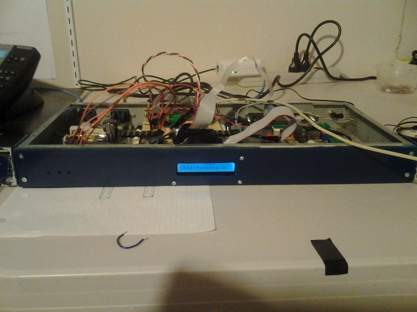
Chassis
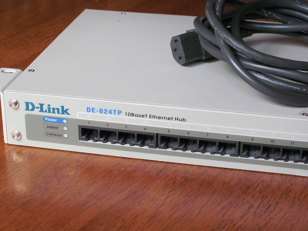
I wanted to rackmount my device so I started to look for anything that
is rackmountable on kijiji. I was looking for a broken device but then
I found this guy who was selling a working hub for 5$. The hub
had a power supply that provides 5V and 12V. Perfect for my project.
So I removed everything inside except the power supply.
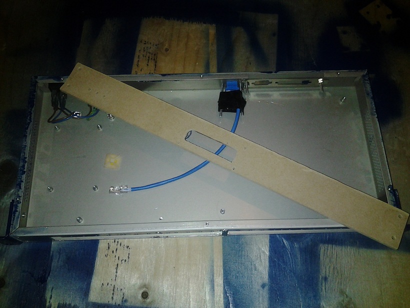
For the front panel, I used a piece of 1/4" MDF and I spray-painted it.
In order to get the PCBs to hold in place in the case, I used a sheet of
lego that I glued on the bottom. Then I made the PCB hold in place with legos.
I had a hard time cutting the holes needed for the terminal board, the LCD
and the RJ45 connector. I used a drill and made several holes until I get this
big ugly rectangle-like hole. For the LCD, it wasn't easy aligning everything. Next time I will
use a CAD and prototype on cardboard first (thanks to ESawDust for the idea).
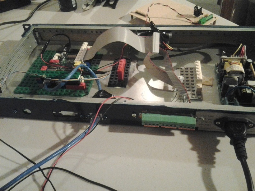
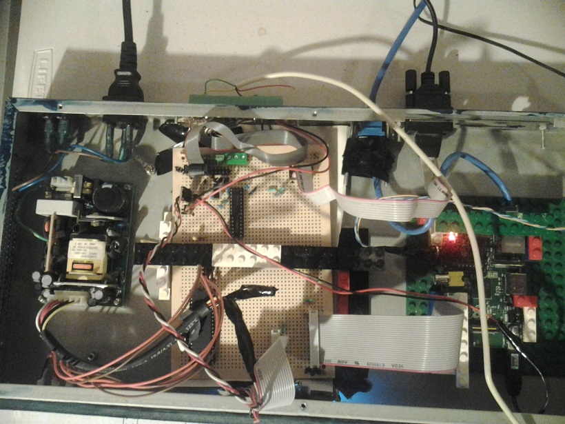
The rPI takes care of the PGM using its GPIO. It communicates to the AVR chip using the SPI bus.
The AVR chip is only used to drive the LCD and the LEDs on the front panel. The terminal board
is used to provide 12V and video connections for my cameras. There is also 4 terminal
used to connect my alarm PGMs (or any other relays, like a motion sensor or a device
to monitor my sump-pump)
The expansion board I did is not very complicated. It is only used for:
- Distribute +5 and +12v over some headers
- Breakout the terminal board on a 2row header
- Add a RS232-to-TTL converter to and RS232 functionality to the rPi
- Add a ATMega1284P to drive some LED and a LCD display on the front panel.
The software
Third party libraries
I had to use the bcm2835 library that was written for interfacing the GPIO in C. For this reason, I had to
licence my code under GPL. When I get some time, I will write my own and use it instead.I hate GPL.
I'd rather just give my code out for free with no strings attached. That's what I usually do. But at least that library is well written and very easy to build and use.
The SIP portion of my software uses resiprocate. I had to cross-compile resiprocate for the ARM platform.
There was a couple of hiccups but it compiled fine. I had to do a couple of tweaks in the source code
and in the makefiles to make it build but nothing too big. Basically what was missing is some references to
the include file "cstddef". I included the file in all failing sources. I also had to modify the Makefile so it would
link against librt too. I've seen bigger problems on other software builds.
I am linking statically to resiprocate so I didn't need to copy anything on the rPI.
I was able to compile LUA for the rPI with "make linux CC=arm-unknown-linux-gnueabi-gcc"
Actualy that command failed. But it doesn't matter because it failed after it was able to create the static library file.
So I copied all the header files and the static library in my source folder and I used it that way.
For ortp (the RTP library), I compiled statically but I deployed it in my toolchain's library folders.
CC=arm-unknown-linux-gnueabi-gcc ./configure --target=arm-unknown-linux-gnueabi --host=x86_64-unknown-linux-gnu --prefix=/opt/arm-unknown-linux-gnueabi/arm-unknown-linux-gnueabi --enable-static
make
make install
I am using Berkeley DB as a storage mechanism for persistant script variables and events. I
downloaded db-5.3.21.NC.tar.gz.
cd buil_unix
../dist/configure -host=arm-unknown-linux-gnueabi CC=arm-unknown-linux-gnueabi-gcc RANLIB=arm-unknown-linux-gnueabi-ranlib STRIP=arm-unknown-linux-gnueabi-strip AR=arm-unknown-linux-gnueabi-ar -enable-smallbuild -prefix=/opt/arm-unknown-linux-gnueabi/arm-unknown-linux-gnueabi CFLAGS="-Os"
make
make install
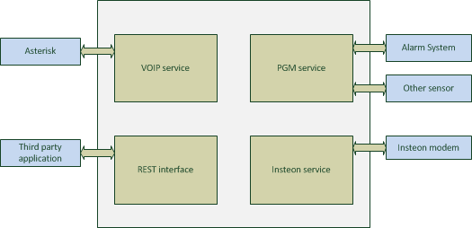
Software architecture
The rPI board runs a home-made server application. The server contains 4 modules that can talk to each other:
- VOIP Service. Used to place calls when a module has an event to report or to receive calls to control one of the other modules.
- PGM Service. Used to monitor triggers such as PGM on an alarm system, sumpump events or a door sensor event.
- Insteon Service. Used to report events received by an insteon modem or to send a command to the modem.
- REST Interface. Used for invoking commands on different modules.
- SMTP server. Used to get emails for events generated by Paradox IP100 module.
- Web Service. Used to get REST requests over HTTP
- Event Processor. Used to receive JSON formatted events from different modules.
I am planning on adding another module eventually to interface my to IR cameras.
REST API
| /alarm/getlogs |
| Retrieve all alarm logs |
| /audio/play |
| plays files defined by PLAY_STRING on onboard sound device |
| sound | Coma separated list of files to play. digits can be used. They will be decoded and the proper sound files will be constructed. I.e: sound1,29,4,sound2 would play sound files: sound1.wav,20.wav,9.wav,4.wav,sound2.wav Note that number reconstruction only work for french grammar and only supports numbers -59..59 inclusively. For playing silence, you can use the number of seconds prefixed by a dollar sign. I.e: sound1.wav,$4,sound2.wav. This would make a 4 second pause between sound1 and sound2 |
| /events/add |
| add a scheduled event. This event will trigger the LUA script at the defined time |
| hour | hour of the day at which to trigger the event |
| min | minute of the hour at which to trigger the event |
| name | Event name |
| p | user defined data |
| /events/gettime |
| get current time |
| /events/remove |
| remove a scheduled event |
| id | event ID |
| /events/show |
| show all scheduled events |
| /help |
| display API documentation |
| /insteon/addezflora |
| add a Insteon ezflora module definition |
| id | the Insteon device ID formated as 0xNNNNNN |
| name | The name of the module |
| /insteon/addiolinc |
| add a Insteon iolinc module definition |
| id | the Insteon device ID formated as 0xNNNNNN |
| name | The name of the module |
| /insteon/addmodule |
| add a Insteon module definition |
| id | the Insteon device ID formated as 0xNNNNNN |
| name | The name of the module |
| /insteon/clearmodules |
| reset list of Insteon module definition |
| /insteon/ezflora/setprogram |
| Sets a program on the EZFlora |
| id | the Insteon device ID formated as 0xNNNNNN |
| p | Program number. 1 to 4 |
| z1 | Zone 1 timer. 0 to 255 minutes |
| z2 | Zone 2 timer. 0 to 255 minutes |
| z3 | Zone 3 timer. 0 to 255 minutes |
| z4 | Zone 4 timer. 0 to 255 minutes |
| z5 | Zone 5 timer. 0 to 255 minutes |
| z6 | Zone 6 timer. 0 to 255 minutes |
| z7 | Zone 7 timer. 0 to 255 minutes |
| z8 | Zone 8 timer. 0 to 255 minutes |
| /insteon/ezflora/status |
| Forces an update of EZFlora status |
| id | the Insteon device ID formated as 0xNNNNNN |
| /insteon/listmodules |
| lists all Insteon modules |
| /insteon/raw |
| Send raw insteon command |
| cmd1 | command byte 1 |
| cmd2 | command byte 2 |
| d1 | data byte 1 for extended data |
| d10 | data byte 10 for extended data |
| d11 | data byte 11 for extended data |
| d12 | data byte 12 for extended data |
| d13 | data byte 13 for extended data |
| d14 | data byte 14 for extended data |
| d2 | data byte 2 for extended data |
| d3 | data byte 3 for extended data |
| d4 | data byte 4 for extended data |
| d5 | data byte 5 for extended data |
| d6 | data byte 6 for extended data |
| d7 | data byte 7 for extended data |
| d8 | data byte 8 for extended data |
| d9 | data byte 9 for extended data |
| id | the Insteon device ID formated as 0xNNNNNN |
| /insteon/refreshalllinksdatabase |
| retrieve all-link database |
| /insteon/setcontroller |
| set Insteon controller ID (PLM) |
| id | the Insteon device ID formated as 0xNNNNNN |
| /insteon/switch |
| Turn on or off a device |
| action | on/off/toggle |
| id | the Insteon device ID formated as 0xNNNNNN |
| level | 0 to 255. Irrelevant if action is off or toggle |
| rate | 0 to 255. This is the ramp rate |
| subdev | for EZFlora, subdev is 1-7 for valves and 8-11 for programs 1-4. For switches, this is irrelevant |
| /panel/lcd |
| Set text on DHAS panel LCD |
| row | row index (0 or 1) |
| str | string to display on LCD |
| /panel/lcd/reset |
| reset DHAS panel LCD |
| /panel/led |
| set LED status on DHAS panel |
| action | on/off/blink |
| id | led index |
| time | duration of LED on or blink. If not provided, 255 will be assumed |
| /pgm/getlogs |
| retrieve full list of logged PGM events. if pgm number is given, only logs for that PGM will be returned. |
| pgm | pgm number [0-3]. Optional |
| /pgm/querypgm |
| retrieve current status of pgm |
| pgm | pgm number [0-3]. |
| /phone/blf |
| Will subscribe for presence events for the given extension. The extension must be a known extension in the subscribe context of our UA (if using Asterisk). |
| ext | extension |
| /phone/call |
| Will call the given extension and optionally play sound when the remote peer answers the call. Placing a call only works if the user agent was previously registered. Called extension must be know by the proxy because direct URI are not supported. To make an intercom call (where the UAS will autoanswer) this needs to be configured on the proxy. |
| ext | extention to call |
| play | Coma separated list of files to play. digits can be used. They will be decoded and the proper sound files will be constructed. I.e: sound1,29,4,sound2 would play sound files: sound1.wav,20.wav,9.wav,4.wav,sound2.wav Note that number reconstruction only work for french grammar and only supports numbers -59..59 inclusively. For playing silence, you can use the number of seconds prefixed by a dollar sign. I.e: sound1.wav,$4,sound2.wav. This would make a 4 second pause between sound1 and sound2 |
| /phone/play |
| Play sounds on an active call using given callID. |
| id | call ID |
| releaseaftersounds | [true/false] if you want the call to be released after sound finished playing |
| sound | Coma separated list of files to play. digits can be used. They will be decoded and the proper sound files will be constructed. I.e: sound1,29,4,sound2 would play sound files: sound1.wav,20.wav,9.wav,4.wav,sound2.wav Note that number reconstruction only work for french grammar and only supports numbers -59..59 inclusively. For playing silence, you can use the number of seconds prefixed by a dollar sign. I.e: sound1.wav,$4,sound2.wav. This would make a 4 second pause between sound1 and sound2 |
| /phone/register |
| Will register the phone service user agent to the given PBX. This is usually done during initialization |
| pin | pin associated to user |
| proxy | PBX IP address |
| user | SIP user to register |
| /phone/release |
| release a call using call ID (usually provided in call events) |
| id | Call ID |
| /phone/showblf |
| Get the list of active subscriptions to presence events in the system |
| /phone/showcalls |
| Get the list of active calls in the system |
| /thermostat/getstats |
| retrieve stats |
| /thermostat/setip |
| set IP of thermostat |
| ip | IP address of thermostat |
| /thermostat/setmode |
| set operating mode |
| mode | cool/heat |
| /thermostat/settemperature |
| Set thermostat setpoint (farenheit) for given mode |
| mode | cool/heat |
| t | temperature in fareinheit (integer) |
| /weather/temperature |
| get current outdoor temperature |
Events
When a module needs to trigger and event, it sends a JSON formatted message to the EventProcessor.
The event processor then executes a function in a Lua script. The Lua script
has a handler that will receive the JSON message. It is up to the user to write his own
Lua script to trigger any desired actions upon receiving an event. The script can trigger
actions by initiating a RESTful request to the application. The script needs to have one function defined:
onEvent(str) which will be called by the EventProcessor.
Timer event that gets triggered every minute of the hour.
{
    "event":"timer",
    "timestamp":"TIMESTAMP"
}
Sun rises in Ottawa, Canada. This will occur at a minute boundary
{
    "event":"sunrise",
    "timestamp":"TIMESTAMP"
}

Sun sets in Ottawa Canada. This will occur at a minute boundary
{
    "event":"sunset",
    "timestamp":"TIMESTAMP"
}

Insteon event
{
    "event":"insteon",
    "id":"device ID",
    "name":"device name",
    "trigger":"unsolicited/ack", ; unsolicited event or ack of a direct message
    "type":"switch", ; only switch for now
    "value":"0..255"
}

PGM state changed
{
    "event":"pgm",
    "pgm":"PGM number", ; 1..4
    "status":"0/1"

}

Phone module event when a call comes it, digits are sent, call is released
and call initiated.
{
    "event":"call",
    "call": {
        "from":"caller"
        "to": "called extension"
        "id": "SIP call ID"
    }
    "callevent":{
        "type":"answered/released/digit"
        "dir": "incoming/outgoing"
        "digit":"digit pressed"
    }
}

SIP Presence events
{
    "event":"presence",
    "device":"SIP device",
    "status":"idle/busy/terminated"
}

IP100 module Alarm events
{
    "event":"alarmstate",
    "time":"time stamp",
    "status":"Armed or Disarmed or Alarm",
    "from":"user that generated the event"
}
User defined scheduled event
{
    "event":"scheduledevent",
    "id":"id"
    "name":"name of event"
    "param":"user defined parameter"
    "min":"minute that event was triggered"
    "hour":"hour that it was triggered"
    "recurent":"true if event will stay in system. false if event will be deleted after being triggered"
}

EZFlora turned off water
{
    "event":"wateroff",
    "id":"ezflora id",
    "name":"device name",
    "type":"1",
    "meter":LITERS_USED, // this is the number of liters used since last start of program or valve
}

EZFlora turned on a valve
{
    "event":"wateron",
    "id":"ezflora id",
    "name":"device name",
    "type":"1",
    "meter":LITERS_USED, // this is the number of liters used since last start of program or valve
    "previousvalve":VALVE_NUMBER: // if another valve was on before, this is the one
    "valve":CURRENT_OPENED_VALVE
}
VOIP module
The phone service will not allow any calls to be placed unless the user agent is sucessfully registered. This is done with the REST
command /phone/register?user=&pin=&proxy=.
The phone service will accept calls for any users (extension) at its address. It
will answer all calls and will trigger an event containing the called extension and all DTMF tones being sent its way.
Insteon
The protocol is a bit difficult to use. I'm not sure why they made so complicated. For example, when sending a "status request" command,
we get a response back but we don't get the command number back in the response. So it is hard to know what that response is for. So
we have to remember that we were waiting for a response like that. It's diffucult to make a nice asynchronous parser. I can think
of a thousand ways to make that protocol easier to use.
When sending an insteon command, you need to wait to get the echo back with a NAK or ACK. If you get an ACK and
you are expecting to get a response from a device after issuing that command, you need to wait for the response.
Things cannot be done in a trully async manner. If you send a whole bunch of commands and expect to get a whole bunch
of responses after, it won't work. So before issuing a command, you need to make sure you got the expected
response of a previous command (or use a timeout). At least it works that way for "Status request". If you send
10 "status request" in a row without waiting for the reponse of each, then you won't get all responses. At least
that's my experience, I don't remember seeing that in the documentation. The only problem with the way I'm
doing things is if I get an unsolicited event (someone opened a light manually) between the echo of my command
and the response I was expecting. I am assuming that the PLM will handle such a case for me and send me the
events in the right order. Otherwise, the protocol has a major flaw in my opinion.
Script
This is where all the power is at.
The server exposes an interface to receive events and trigger actions. The server does not care
about which action should occur when an event occurs on a module. This is handled by a Lua script.
So with a script like this, I can tell my device to do many things upon receiving an event. I can
make a script that says "when you receive a call from device X and he sends digits 1234, turnon the bedroom light"
or "when PGM 2 gets activated (by motion sensor in staircase), play sound alarm.wav on rPI analog output" or "at 7PM, turn on outside light"
or "when PGM 1 is deactivated (alarm system disarmed), send a call in living room and play greeting.wav".
Here is an example of a Lua script for a system:
initiateAction("/insteon/setcontroller?id=0x123456");
initiateAction("/insteon/clearmodules");
initiateAction("/insteon/addmodule?name=bedroom&id=0x7F1FBA");
initiateAction("/phone/register?user=username&pin=password&proxy=172.2.88.8")

function onEvent(st)
    JSON = (loadfile "JSON.lua")()
    local v = JSON:decode(st)
    if v["event"]=="pgm" and v["pgm"]=="1" and v["status"]=="0" then
        initiateAction("/insteon/switch?id=0x1FAA22&action=on")
    end
end
The first lines in the global scope will be executed when the server starts or whenever the script is
reloaded. This is a good place to do initialization. In my example, it is where I initialize my insteon devices.
These lines are necessary since the server needs to know about the insteon devices. Then there is the onEvent
handler. This function will be called whenever an event occurs on a system module. This is where the power of
Lua comes into play because I can apply any logic I want using the Lua script. The script will always stay loaded
so if a event occurs and the script sets a global variable, this variable will still hold the same value
upon receiving the next event. This is true only until the script is reloaded though.
Since all global variable values are lost after a script is reloaded, 2 functions are provided to the Lua scripts:
getVar(key) and setVar(key,value). These two functions provide peristant storage of values even when the server is restarted.
My server listens for SIGHUP. So whenever the script is modified, issuing "killall -HUP homeautomation" will reload the script
System configuration
This is how I use my device
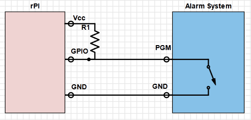
Alarm system
My alarm system allows me, with the use of a jumper on the board, to specify if I want the PGM to source 12V or sink to ground.
I configured it to sink to ground. That way, the PGM will act like a switch. When PGM is activated, it will be connected to ground,
when deactivated it will be disconnected. So with a pull-up resistor to the 3.3V pin of the rPI, the GPIO on the rPI will get 0 or 3.3 V
depending on the status of the PGM. I configured one of my PGM to activate/deactivate following the arm status of a partition. The second
PGM is configured to activate when any of the zones are in alarm and deactive when any of the zone alarms are restored.
Insteon
I currently have 4 light switches. 1 in my bedroom, that turns on in the morning when I get my wakeup call. I
have another one for the outside light at the front door. This one gets turned on based on a schedule (sunset until midnight). Another one in the living room gets turned on when the alarm system gets deactivated between sunset and sunrise. The other one is in my basement and has no special purpose.
I use my EZFlora to water my two vegetable gardens at 5 in the morning. I can cancel a scheduled watering or schedule another one.
Features
Alarm status web page
I configured my alarm system to activate/deactivate a PGM (a relay on the alarm system) when we arm/disarm the system.
The rPI monitors the PGM using a GPIO pin. The rPI logs all activity about the PGM in a local file. This is done
by a homemade server application. The server application also listens for RESTfull queries on a TCP port. Now
any computer in my house (including my tablet and smartphone) can make a request to the rPI using a webbrowser
and it wil get a JSON formatted response indicating the status of the alarm system or a list of arm/disarm
events with a timestamp. This is usefull to know if someone is at home while I am away or to know if the system
is currently in alarm.
When I bought my alarm system, I got an IP module that lets me receive
events and can let me configure the system. The module isn't that great though.
The only events I can receive are email notification of who armed/disarmed
the system or which zone is in alarm. I'd like to get more events but I guess
I'll have to live with that. The fact that I can only get email notifications
also annoys me. I have to specifiy the SMTP server but it absolutely needs
to be a domain name with a MX record (no IP address). So I had to hack the
following into place:
- Install bind on the rPi and create a zone with an MX record.
- Make a fake SMTP server that receives the emails and parses them.
The SMTP server is a module in my homeautomation system instead of a stand
alone SMTP server. It is just a module that listens on port 25. The DNS
server (bind) has a zone that resolves an MX record to the address of my
home automation system. The alarm system IP module has been configured to use
that DNS server. When the SMTP server module receives an email, it parses it
and trigger to appropriate event It is a complicated setup and it is a shame that I need
to use it that way. But now, at least, I have a way to know who
armed/disarmed the alarm system and when it occured.
I am currently using the alarm system PGM to know if the system is armed
or disarmed. This is very reliable because if an event occurs while my
software is down, I can always check the PGM status on load. But I also
use the SMTP server to get notifications of who armed and disarmed the system
to trigger a welcome call on the phone close to the front door. The welcome
call greets me and tells me how many voicemails I got while I left.
The voicemail announcement depends on who disarms the alarm, because we each
have our own voicemail box.
Phone System
Since I run an Asterisk server at home, all my phones are IP phones. With this in mind, I decided to leverage that
in order to call my device and send it DTMF tones to control different actions. So with a phone in the house,
I can turn on/off lights and trigger any other actions that my device is capable of. I also have
an Aastra phone that has some buttons I can assign XML web pages on. When pressing a button, it fetches
an XML document at a URL of my choice and displays the content on the phone. I don't really care about the XML.
With these buttons, I execute some REST commands on my device to turn on/off my bedroom lights and setup a wakeup call.
Download
You will not be able to compile the source code because I didn't include any of the GPL stuff. But you couldn't use it any way if you don't have my device. So here is the source code and I hope that at least bits of it will help for other projects. dhas.tar
I recently bought an Insteon irrigation controller called the EZFlora. In this article, I will describe how the controller
works and how to use it from scratch with a PLM. I am not using any well-known software to control my Insteon devices. This
information is usefull for people building their own software and communicate directly with the PLM .
Before going any further, basic knowledge of how to send standard and extended commands to a PLM is required. This is part of my Home Automation system. You can find an example source code in that Home Automation system article.
The EZFlora is a 8 zone irrigation controller. It allows me to control up to 8 solenoid valves for my garden.
The EZFlora lets you open/close a valve or run a program. A program is a sequence of timers. It is possible
to make 4 different sequences. A sequence is represented internally by an array of 8 bytes that represents the runtime
in minutes of each valve. Byte 0 is for valve 0, byte 1 is for valve 1 etc. Programs are very usefull because your
application sends a command to start a program (sequence) and just waits for the results. If your application
would open a valve and for some reason the application crashed, hung or communication with EZFlora would go down (or any other reasons),
then you could not send a "valve off" message. With a program, you leave it to the EZFlora to do everything.
An application "uploads" such programs by sending the "set sprinkler timers" extended command.
CMD1 is 0x40, CMD2 is the program number (0-4) and the first 8 extended bytes represent the sequence.
Note that this will store the program into eeprom. The program numbers are from 1 to 4. Program number 0 is the default
timers. Default timers are used when a valve is opened with the "valve open" command. After the timeout expires, the
valve will close. This is usefull in case you would forget to close the valve.
My server initially sends a "sprinkler control" command to enable valve status messages. These messages
are broadcast messages. The annoying thing is that the PLM will not forward those events to your application.
So my server needed to put the PLM in "monitor mode" using command 0x6B (see the 2412 Dev guide). It
is really important that you do this, otherwise you will not receive any of the broadcast events. The EZFlora
also needs to be in the PLM's All-Link database.
One nice thing is that any "sprinkler control" command sent, will return a status byte in the ACK message. So by
sending such a command, I am also requesting the system status indirectly. Now every time a valve
status changes, I will also receive a message that contains the status byte. The status byte tells me
what valve is currently opened and what program is running (if any). As the command set document
indicates, the status event broadcast message also contains the water meter counter hidden in the
"To Address". So bascially, when I send a command to start a program, I get the valve/program status in the ACK
message. Then everytime the program activates another valve, I get a broadcasted message with the valve/program status
and the meter counter value. And the end of the program, I can see in the event that the program is not running anymore
and using the meter counter I know how much water was used during the whole program. Note that when a program turns off
a valve and opens the next one, it broadcasts only one event with the newly opened valve number. This is fine since
the EZFlora always activates one zone at a time. So when you see that valve X is opened, it is safe to assume
that all other valves are closed.
Water meter counter
It is possible to attach a water meter counter to the EZFlora and get events every time the meter makes a pulse.
The meter I was looking at generates 450 pulses per liters. That would generate way too much traffic.
So I decided to leave the "Meter count change" event off. Instead, I reset the counter everytime I send a
start valve or start program command. And I look at the meter count every time I get a status message.
When I get a status message that says that no program is running, I can deduce that it was because
a program has terminated so I check the meter count and I know how much water I used while the program
was running.