WRITING A HYPERVISOR WITH INTEL VT-X
2017-06-21

Introduction
Before virtualization support was available on CPUs, virtual machines were emulating most of the code that a guest OS would run.
With VMX, the CPU handles the virtualization. If you are familiar with the hardware context-switches that were available
on ia32, it's a bit similar. The hypervisor manages many VMs. When executing code of a VM, there is a hardware context switch
that occurs. The context switch saves the current CPU state (but not the general purpose registers) and loads another
state that would be the one of the VM. Then code can execute from there. So the VM ends up running "bare-metal". The CPU
has changed it's entire context and runs your VM just as it would if the guest was running bare-metal. With one exception:
Some operations causes VMExits. For example, when an interrupt occurs, the CPU automatically switches back to the hypervisor
context (what they call the VMM). The VMM can then handle the interrupt and change the Guest's state data so that on the next
entry it will think it has an interrupt to handle (or not). This is basically how you would handle the timer interrupt
on the guest and on the host so that multithreading works. VMExits occur for many other reasons. You could have a VMExit
occur when the VM tries to access unmapped memory, when executing "hlt" or many other reasons.
For other articles about my OS:
Networking in my OS
virtio driver implementation
Process Context ID and the TLB
Thread management in my hobby OS
Enabling Multi-Processors in my hobby OS
Memory Paging
AVX/SSE and context switching
Stack frame and the red zone (x86_64)
To view the full source code of my OS: https://github.com/pdumais/OperatingSystem
Goal
The virtual environment we'll be setting up is for a 16bit real mode VM because that's how a real CPU would start.
Control will initially be transfered to address 0x00000000. Normally, an entry point to BIOS code should be located there
and then the BIOS would eventually load the first sector of the primary HDD and transfer control to 0x7c00. But in my case,
I am not writting a BIOS, so only test code will be executed in the VM.
Memory
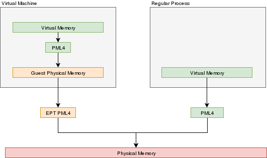
In a VMX environment, there exists several layers of memory:
- Guest virtual memory: The guest's virtual memory if paging is enabled in the Guest. That memory translates
to guest physical memory using the guest's paging structures, entirely controlled by the guest.
- Guest physical memory: This is the physical memory from the VM's point of view. From the hypervisor's point
of view, this is just virtual memory that has to be mapped to physical memory. This memory would be
allocated lazily as the VM uses more and more memory. This memory is mapped to physical memory
by the hypervisor.
- Physical memory: This is the real hardware physical memory as seen by the host's CPU.
For more details about how paging works, please refer to Memory Paging
For the VM to have memory, some of the host's physical memory must be assigned to the VM. The guest's physical memory is seen as
virtual memory by the host. To assign memory to the guest, a feature provided by the CPU called "EPT" can be used. EPT works
Just like the regular paging system. It is a way to map guest-physical addresses to real physical addresses using a paging
structure with a PML4 table on top.
So a guest would prepare it's own internal paging system and have it's own PML4 table. When an a virtual address inside the VM
needs to be resolved, it will be resolved to the guest's physical address using its PML4 table. Then, the guest-physical address
will be resolved using the EPT's PML4 table. So 2 translations would be done.
EPT is enabled by setting the "Enable EPT" bit in the VM-Execution controls. When enabled, an EPT PML4 structure
must be prepared and and the base address of that structure must be stored in the VMCS EPT pointer
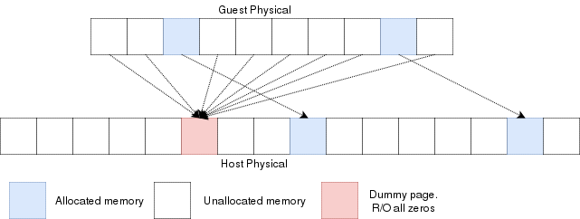
Lazy allocation of guest physical memory
When a guest is launched with, for example, 16gb of ram, it would not be desirable to reserve that entire
memory on the hypervisor immediately. Instead, it would be preferable to allocate that memory in a lazy allocation
fashion. A guest might never use it's entire RAM so reserving it on the hypervisor would be a waste.
Reading an unallocated guest physical page will return zeros. Writing to it will trigger a EPT violation. The VMM can then reserve
a physical page and map it there instead of the dummy page.
When the guest is launched, a single page of write-protected physical memory (filled with zeros) should be mapped to all the guest
physical memory. If the VM's BIOS starts probing memory by reading all of it, every 4k would be mapped to that single page so the BIOS would read zeros and think it is
reading valid memory. If the BIOS (or the guest OS) writes into
memory, a VMexit would occur because writing to any address would map to this write-protected physical page.
The hypervisor can then allocate a new R/W page to the EPT's paging structure for the guest physical memory. Of
course, if the guest does a write/read-back kind of algorithm the probe the memory, then all the guest physical
memory will have been allocated because all pages will have been written to, so all bets are off.
Reclaiming freed-up memory is a different story. The only way the hypervisor can
know about memory that can be reclaimed is by using memory balooning. The virtio
specification describes a memory baloon device that can be implemented for that
purpose.
When the guest will access guest-physical memory that is unmapped to physical memory, a VMExit will occur.
The hypervisor needs to evaluate if the guest-physical address falls into the possible addressing space of the VM
(i.e. if it is trying to access memory beyond the last byte of the virtual RAM). If the memory is unmapped
because of the lazy-loading scheme, then a new page can be allocated. If it is because that memory address should
not be mapped, then an exception will be injected back in the VM and the guest will need to handle that.
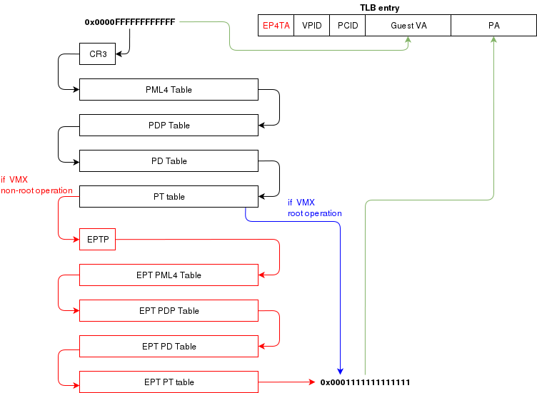
Translation Lookaside Buffer (TLB)
When the process translate a virtual address to a physical address, the translation is cached in the TLB so that
it wont have to walk through the page tables again next time. In a virtual environment, the CPU only has one TLB
in which is caches translations for:
- All host virtual/physical mappings
- All guest-physical/physical mappings (of all VMs)
- All guest-virtual/guest-physical mappings (of all VMs).
This could create collisions in the TLB. For example, 2 VMs could have a mapping of virtual address 0x00000000. A simpler
case would be two processes with different virtual memory mappings running on the host. For this reason, as I described in
another article (Process Context ID and the TLB), the TLB supports processID-tagging. With VMX, two new taggings exist: VPID and EP4TA.
VPID is the tagging of a TLB entry for a specific virtual CPU. This is only tru if VPID is enabled in the VMCS and if a non-zero
VPID has been set in the VMCS. In such a case, every guest-virtual to guest physical translations that are inserted in the TLB
will be tagged with the current VPID. This means that another VCPU can insert a similar entry in the TLB and it will be tagged
with a different VPID. When the MMU looks up a mapping in the TLB, it will only consider those tagged with the current VPID.
EP4TA tagging is done when EPT is enabled. Every guest-virtual to host-physical (going through EPT tables) are cached in the TLB
with a tagging of the current EPT,PCID and VPID. The EPT ID (EP4TA) is derived from the current EPTP, so there is no specific
ID to set, unlike PCID and VPID.
If VPID is not enabled, then the VPID tag is always 0 and is always ignored during lookups. A lookup while EPT
is active (during non-root operation) will only consider entries with a matching EP4TA.
I'm a bit confused by what the Intel documentation says about EPT and the TLB. From what I can understand,
it seems like the TLB will cache guest-virtual mappings to host-physical addresses. Those are called "combined mappings"
When EPT is enabled, these entries will be tagged with the current EP4TA,VPID,PCID.
If VPID is not enabled:
- entries will be tagged with VPID=0.
- On vmexit/vmentry, all entries with VPID==0 will be invalidated, regardless of EP4TA tag.
For this reason, I am enabling VPID with a tag of "1" for all my VCPUs. The documentation clearly states that having the same VPID
for different EPT is acceptable.
When the guest will invoke "invlpg" or "invpcid", these instructions should be trapped because they will invalidate all
requested TLB entries regardless of the current EP4TA. So the VMM should set a VMExit on those operations and emulate them
using "invept. That's what I am understanding from section 28.3.3.1, but section 28.3.3.3 says that when EPT is enabled, there is
no need to emulate these instruction.
When to invalidate
When a VMExit occurs because of an EPT violation, the faulting page will always be invalidated in the TLB. In my OS,
I use the EPT violation handler to allocate more memory to the VM. When the VM resumes, the TLB will be up to date the VM
will be writing data in the correct physical page. If the VM is rescheduled on another core where the stale TLB entry exists
for that address, then it will be accessing the wrong physical page. The TLB was only invalidated on the CPU that detected
the EPT violation. For this reason, the host needs to do a TLB shootdown on all host CPUs. This done by sending a IPI to
all other CPUS. The CPUS will then execute "invept" to invalidate TLB entries associated with the EPT in question.
The "invept" can be used to invalidate ALL tlb entries tagged with a specific EPT, or all EPT.
Initialization
The initialization of vmx mode is well described. There are a couple of web sites with examples that can be found using a simple
google search. But the Intel SDM #3 describes an algorithm to do so. Basically, this is what needs to happen:
- detect support for VMX
- create a VMCS for vmxon
- execute vmxon
- create a VMCS for a VM and write all required data in it
- run vmlaunch
It's important to note that VMXON should be executed on all CPUs and this should be done when the hypervisor starts.
In my OS, I do this as soon as I switch to long mode on all cores and I leave it on all the time.
The tricky part is to get the VMCS for the guest initialized correctly. I had to spend quite some time
fine-tunning the fields. If VMLAUNCH fails, the zero flag will be set, then you can do a VMREAD to VM_INSTRUCTION_ERROR
to get the error code. Then, the SDM (chapter 26) describes all the checkings that the CPU does so you can
walk through those and make sure your code is compliant.
Also, it seems like access rights and segment limits for guest segment descriptors still need to be properly set even if
the VM will run in real mode. If I recall correctly, it's because they will be checked even in real mode and
that is how "unreal mode" works.
I am not going in the details about this because everyone talks about that and the SDM has very good documentation
about it.
Multi-tasking (in a multi-core environment)
Running a VM in a multitasking environment requires a bit of logic that is beyond that the Intel manuals describe. This is because
a VM really is just a process getting a time slice with the scheduler. So when the process is scheduled out, the entire VM is paused.
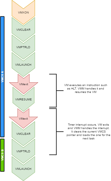
Every VCPU is managed by one and only one thread in the OS. So each thread has a VMCS (if it is running a VCPU)
Before the task get's scheduled out, vmclear is executed so that any cached data gets flushed in the VMCS.
At least that's what Intel recommends to do. When a task is scheduled back in, VMPTRLD is executed to load the VMCS (if any) that
this task manages.
When a timer interrupt occurs and it's time to do a context switch on the host, since the VM runs as part of
a process on the host, it is normal that it gets interrupted and that time is given to another process.
That process might want to run a VM also, or maybe it's just a normal application. When the timer interrupt occurs,
this will trigger a VMExit and the CPU will be back at executing code in the context of the host. The thread will change.
When getting back to this thread, we will do a VMRESUME to continue executing the VM. We will also reload the VMCS
with VMPTRLD because another process might have loaded another VMCS. We could even be running on another processor
in a multi-core system. And remember, loading a VMCS is only loaded on the current core. So with 4 cores,
you could have 4 different VMs running
When the VMM is running in root-operations because of a VMexit, it could have been scheduled out at any moment before doing the
VMRESUME. So when VMRESUME is executed, it is possible that VMCLEAR was executed before because of a task switch. For this
reason, the OS checks if VMRESUME fails and executes VMLAUNCH instead.
The OS should avoid scheduling VCPUs from cores to cores because moving a VCPU to another core makes it mandatory to do a VMCLEAR.
My OS does not make such effort and blindly does a VMCLEAR on every task switch. So performance could be improved there.
And interesting point here is that after executing VMLAUNCH, control never returns to the calling function (unless vmlaunch fails).
VMLAUNCH and VMRESUME will jump in the guest's code without pushing a return address. A VMExit handler has been defined in the VMCS,
so from the host's point of view. control skips from vmlaunch to the handler. Also, since the stack is setup in the host's section
of the VMCS, the VMM gets a brand new stack everytime the VMExit handler gets called. This means that there is no need to pop the
stack before executing VMLAUNCH/VMRESUME
VM Exits
When the cpu is running in non-root operation (running VM code), it's pretty much as if the VM
was running bare-metal. But Several events can make the VM exit back to root-operation (the hypervisor).
A VM exit will restore the CPU state back to what it was set in the VMCS before vmlaunch. The hypervisor
must determine what caused the VMExit and take proper action. VMExits are similar to interrupts because
the general purpose registers are not automatically saved. A VMExit handler must save the registers and
restore them before resuming the VM otherwise the VM will be corrupted. As per the host section of the
VMCS though, a separate stack is being set. The VMM could alter the VM state by changing data in the
VMCS before resuming the VM. For example, if the VMExit occured because of an exception of type #UD,
the VMM could emulate the invalid instruction and change general purpose registers and flags in the VM.
Interrupts
When an interrupt needs to be delivered to the host, a VMExit will occur and control will be immediately
given to the VMM's exit handler. At that moment interrupts will be disabled (flags.IF=0).
When bit 15 (Acknowledge interrupt on exit) is cleared on the VM Exit control, the interrupt is not acknowleged by the processor. This means that as soon as the "IF" flag becomes 1 (ie, when executing "sti"),
the interrupt handler will get called.
In my hypervisor, if such a VM exit is detected, the kernel executes "sti" and finally
"vmresume". This will let the host execute the handler as soon as interrupts are re-enabled, then
control will be handed back to the VMM exit handler to execute "vmresume"
It is worth noting that it doesn't seem to matter if interrupts were cleared before VMLAUNCH.
Interrupts will still trigger a VMExit and the interrupt will be pending until the VMM enables them (using "sti")
Multiple VCPU
supporting multiple VCPUs for a VM requires having 1 VMCS per VCPU (just as if they were all used in independent VMs).
But the hypervisor has to make those CPUs dormant until a "Startup IPI" is sent. From there, the hypervisor can configure
the VCPU to start executing code at the desired address. But the main thing here is that only one VCPU would be started
when the VM is launched. My OS does not yet support this. I am focussing on 1 VCPU for now
One thing to consider when running multiple VCPUs is that one of them could trigger a VMExit because of a memory
allocation requirement (as described in a previous section of this article). In such a case, another VCPU could be running,
or the current thread could get scheduled out with another VCPU one being scheduled in. So extra care
should be taken to ensure that memory does not get corrupted.
Other thoughts
There are many other things to consider to improve performances and to make the design robust
Things to consider are:
- Trapping "hlt" with a vmexit so we can schedule out an idle VCPU
- Trapping TLB/MMU operations to better manage memory
- Trapping IO operations so that the hypervisor can retain control over hardware.
- Setup a virtual apic so that VCPUs can receive interrupts (and make a scheduler).
The code
For reference, this is a part of my VMX code:
What next?
There is still some work to be done for implementing a full hypervisor. The work done here only creates
virtual CPUs. The hypervisor needs to emulate other hardware such as a hard drive, a network card, a video card, keyboard etc.
I would probably write virtio devices since they are easy to code and very efficient.
Another big part that is missing is a BIOS. The hypervisor has to provide a BIOS for your guests since they rely on that to boot.
CREATING YOUR OWN LINUX CONTAINERS
2016-07-10
I'm not trying to say that this solution is better than LXC or docker. I'm just doing this because
it is very simple to get a basic container created with chroot and cgroups. Of course, docker provides
much more features than this, but this really is the basis. It's easy to make containers in linux, depending
on the amount of features you need.
cgroups
cgroups are a way to run a process while limiting its resources such as cpu time and memory. The it works is by creating a group (a cgroup),
define the limits for various resources (you can control more than just memory and CPU time) and then run a process under that cgroup.
It is important to know that every child process of that process will also run under the same same cgroup. So if you start a bash shell
under a cgroup, then any program that you manually launch from the shell will be constrained to the same cgroup than the one of the shell.
If you create a cgroup with a memory limit of 10mb, this 10mb limit will be applicable to all processes running in the cgroup. The 10mb
is a constraint on the sum of memory usage by all process under the same cgroup.
Configuring
On slackware 14.2 RC2, I didn't have to install or setup anything and cgroups were available to use with the tools already installed. I had to manually
enable cgroups in the kernel though since I compiled my own kernel. Without going into the details (because this is covered in a million other websites)
you need to make sure that:
- cgroup kernel modules are built-in are loaded as modules
- cgroup tools are installed
- cgroup filesystem is mounted (normally accessible through /sys/fs/cgroup/)
Here's how to run a process in a cgroup
cgcreate -g memory:testgroup
# now the "/sys/fs/cgroup/memory/testgroup" exists and contains files that control the limits of the group

# assign a limit of 4mb to that cgroup
echo "4194304" > /sys/fs/cgroup/memory/testgroup/memory.limit_in_bytes

# run bash in that cgroup
cgexec -g memory:testgroup /bin/bash
Note that instead of using cgexec, you could also just write the current shell's PID into
/sys/fs/cgroup///task. Then your shell, and whatever process you start from it, would execute
in the cgroup.
Making your own containers
A container is nothing more than a chroot'd environment with processes confined in a cgroup.
It's not difficult to write your own software to automate the environment setup. There is a "chroot"
system call that already exist. For cgroups, I was wondering if there was any system calls available
to create them. Using strace while running cgcreate, I found out that cgcreate only manipulates files
in the cgroup file system. Then I got the rest of the information I needed from the documentation
file located in the Documentation folder of the linux kernel source: Documentation/cgroups/cgroups.txt.
Creating a cgroup
To create a new cgroup, it is simply a matter of creating a new directory under the submodule folder that
the cgroups needs to control. For example, to create a cgroup that controls memory and cpu usage, you
just need to create a directory "AwesomeControlGroup" under /sys/fs/cgroup/memory and /sys/fs/cgroup/cpu.
These directories will automatically be populated with the files needed to control the cgroup (cgroup
fs is a vitual filesystem, so files do not exist on a physical medium).
Configuring a cgroup
To configure a cgroup, it is just a matter of writing parameters in the relevant file. For example:
/sys/fs/cgroup/memory/testgroup/memory.limit_in_bytes
Running a process in a cgroup
To run a process in a cgroup, you need to launch the process, take its PID and write it under /sys/fs/cgroup///task
My "container creator" application (let's call it the launcher) does it like this:
- The launcher creates a cgroup and sets relevant parameters.
- The launcher clones (instead of fork. now we have a parent and a child)
- The parent waits for the child to die, after which it will destroy the cgroup.
- The child writes its PID in the /sys/fs/cgroup///task file for all submodules (memory, cpu, etc)
- At this point, the child runs as per the cgroup's constraints.
- The child invokes execv with the application that the user wanted to have invoked in the container.
The reason I use clone() instead of fork, is that clone() can use the CLONE_NEWPID flag. This will create
a new process namespace that will isolate the new process for the others that exist on the system. Indeed, when the cloned process queries its PID it will find that it is assigned PID 1. Doing a "ps" would not list other processes that run on the system since this new process is isolated.
Destroying a cgroup
To destroy a cgroup, just delete the /sys/fs/cgroup// directory
So interfacing with cgroups from userland is just a matter of manipulating files in the cgroup file system.
It is really easy to do programmatically and also from the shell without any special tools or library.
My container application
My "container launcher" is a c++ application that chroots in a directory and run a process under a cgroup that it creates.
To use it, I only need to type "./a.out container_path". The container_path is the path to a container directory that contains
a "settings" files and a "chroot" directory. The "chroot" directory contains the environment of the container (a linux distribution maybe?)
and the "settings" file contains settings about the cgroup configuration and the name of the process to be launched.
You can download my code: cgroups.tar
Example
I've extracted the slackware initrd image found in the "isolinux" folder of the dvd.
cd /tmp/slackware/chroot
gunzip < /usr/src/slackware64-current/isolinux/initrd.img  | cpio -i --make-directories
Extracting this in /tmp/slackware/chroot gives me a small linux environment that directory and I've created a settings file in /tmp/slackware.
Call this folder a "container", it contains a whole linux environment under the chroot folder and a settings file to indicate under
what user the container should run, what process it should start, how much ram max it can get etc. For this example, my settings file is like this:
user: 99
group: 98
memlimit: 4194304
cpupercent: 5
process:/bin/bash
arg1:-i
And running the container gives me:
[12:49:34 root@pat]# ./a.out /tmp/slackware
Mem limit: 4194304 bytes
CPU shares: 51 (5%)
Added PID 9337 in cgroup
Dropping privileges to 99:98
Starting /bin/bash -i

[17:26:10 nobody@pat:/]$ ps aux
USER       PID %CPU %MEM    VSZ   RSS TTY      STAT START   TIME COMMAND
nobody       1  0.0  0.0  12004  3180 ?        S    17:26   0:00 /bin/bash -i
nobody       2  0.0  0.0  11340  1840 ?        R+   17:26   0:00 ps aux
[17:26:14 nobody@pat:/]$ ls
a  a.out  bin  boot  cdrom  dev  etc  floppy  init  lib  lib64  lost+found  mnt  nfs  proc  root  run  sbin  scripts  sys  tag  tmp  usr  var
[17:26:15 nobody@pat:/]$ exit
exit
Exiting container
Networking
When cloning with CLONE_NEWNET, the child process gets a separate netwrok namespace. It doesn't see the host's network interfaces anymore.
So in order to get networking enabled in the container, we need to create a veth pair. I am doing all network interface manipulations
with libnl (which was already installed on a stock slackware installation). The veth pair will act as a kind of tunnel between
the host and the container. The host side interface will be added in a bridge so that it can be part of another lan. The
container side interface will be assigned an IP and then the container will be able to communicate wil all peers that are
on the same bridge. The bridge could be used to connect the container on the LAN or within a local network that consists
of only other containers from a select group.
The launcher creates a "eth0" that appears in the container. The other end of the veth pair is added in a OVS bridge. An ip address is set on eth0 and the default route is set. I then have full networking functionality in my container.
Settings for networking
bridge: br0
ip: 192.168.1.228/24
gw: 192.168.1.1
Result
Mem limit: 4194304 bytes
CPU shares: 51 (5%)
Added PID 14230 in cgroup
Dropping privileges to 0:0
Starting /bin/bash -i

[21:59:33 root@container:/]# ping google.com
PING google.com (172.217.2.142): 56 data bytes
64 bytes from 172.217.2.142: seq=0 ttl=52 time=22.238 ms
^C
--- google.com ping statistics ---
1 packets transmitted, 1 packets received, 0% packet loss
round-trip min/avg/max = 22.238/22.238/22.238 ms
[21:59:36 root@container:/]# exit
exit
Exiting container
VIRTIO DRIVER IMPLEMENTATION
2016-06-06
Virtio
Virtio is a standard for implementing device drivers on a virtual machine. Normally, a host would emulate a device like a rtl8139 network card, the
VM would detect such a device and would load a driver for it. But this adds a lot of overhead because the host is emulating that device
so it must translate the data it receives into a format that is understood by the real hardware. The more complicated the emulated device it, the more
challenge it will be for the host to keep latency low.
Virtio solves this problem by letting the host expose a Virtio device. A virtio device is a fake device that will be used by the VM. Virtio devices are very
simple to use compared to other real hardware devices. For example, a host may implement a Virtio network card. The VM would detect such a device and
start using it as its network card. Of course, the end-user wouldn't really notice this. The simplicity of the device is seen by the device driver implementers.
So to use Virtio, the host must support it. Currenly, KVM does. Then the guest must install the appropriate device drivers. Virtio device drivers are included
in the linux kernel already, so there is no need to download separate drivers. On windows, drivers must be downloaded separately.
Virtio can be seen as a two layer device architecture. The first layer is the communication layer between the host and the guest. This is how both exchange
information to say "Here's a packet I want you to send on the real hardware" or "Here's a packet I just received from the real hardware".
Note that the driver knows it is running in a virtual environment and can implement optimizations in that effect. But the rest of the OS, using the Virtio
driver, doesn't know that. It only knows that it is using a network card with a driver like any other ones.
Every Virtio device drivers communicate with the host using the same model. This means that the code for this layer can be shared between all Virtio drivers.
The second layer is the protocol used over the first layer. Every virtio device use a different protocol. For example, a virtio-net driver will speak
differently than a virtio-block driver to the guest. But they would both convey the messages the same way to the host.
My OS
The reason I was interested in virtio was because my hobby operating system required some device drivers to work. I had already written
an ATA driver and a netcard driver (rtl8139) but those are old devices and I wanted to learn something new anyway. By having implemented
virtio drivers in my OS, I should, technically, be able to run my OS on any host that support virtio. I don't need to worry about
developing several device drivers because different hosts support different hardware. If virtio because a widely accepted standard (maybe it is already),
then my OS should be fine on all different hosts. Note that I will still need to implement several different drivers if I want to support
my OS on real hardware. But running it in a VM for now is just fine.
My code
These are the drivers. Note that, without the full code of my OS, these drivers won't make much sense but I'm putting them here
in case someone could use it as an example whenever trying to write such a driver.
virtnet.c
virtblock.c
virtio.c
virtio.h
Information
Implementing the virtio drivers was very simple. I was able to do so by using only two sources of information:
Implementation
I'm going to describe the implementation using pseudo-code and will skip some of the basic details. Things like PCI enumeration
will be left out since it is out of the scope of this document.
Device setup
Pci enumeration
The first thing to do is to discover the device on the PCI bus. You will be searching for a device with vendor ID 0x1AF4 with device ID between 0x1000 and
0x103F. The subsystemID will indicate which type of device it is. For example, susbsystem ID 1 is a netcard. So after finding device on the PCI bus, you
will obtain the base IO address and IRQ number. You can then proceed to attaching your device driver interrupt handler to that IRQ and setup the device
using the IObase address..
    foreach pci_dev
        if pci_dev.vendor == 0x1AF4 && pci_dev.device >= 0x1000 && pci_dev.device <= 0x103F && pci_dev.subsystem == 1
        {
            return [pci_dev.iobase, pci_dev.irq];
        }
Init sequence
The device initialization is very well described in the spec so there is no need to go into much details here. Here is the sequence:
    //Virtual I/O Device (VIRTIO) Version 1.0, Spec 4, section 3.1.1:  Device Initialization

    // Tell the device that we have noticed it
    OUTPORTB(VIRTIO_ACKNOWLEDGE,iobase+0x12);
    // Tell the device that we will support it.
    OUTPORTB(VIRTIO_ACKNOWLEDGE | VIRTIO_DRIVER,iobase+0x12);

    // Get the features that this device supports. Different host may implement different features
    // for each device. The list of device-specific features can be found in the spec
    INPORTL(supportedFeatures,iobase+0x00);

    // This is called the "negotiation". You will negotiate, with the device, what features you will support.
    // You can disable features in the supportedFeatures bitfield. You would disable
    // features that your driver doesn't implement. But you cannot enable more features
    // than what is currently specified in the supportedFeatures.
    negotiate(&supportedFeatures);
    OUTPORTL(supportedFeatures,iobase+0x04);

    // Tell the device that we are OK with those features
    OUTPORTB(VIRTIO_ACKNOWLEDGE | VIRTIO_DRIVER | VIRTIO_FEATURES_OK,iobase+0x12);

    // Initialize queues
    init_queues();

    c |= VIRTIO_DRIVER_OK;
    OUTPORTB(VIRTIO_ACKNOWLEDGE | VIRTIO_DRIVER | VIRTIO_FEATURES_OK,iobase+0x12);
    OUTPORTB(c,dev->iobase+0x12);
The init_queues() function will discover all available queues for this device and initialize them. These queues are the core communication mechanism
of virtio. This is what I was refering as the first layer. I will go in more details about queues a bit later. For now, to discover the queues,
You just need to verify the queue size for each queue. If the size is not zero, then a queue exist. Queues are addressed with a 16bit number.
    q_addr = 0
    size = -1
    while (size != 0)
    {
        // Write the queue address that we want to access
        OUTPORTW(q_addr,iobase+0x08)
        // Now read the size. The size is not the byte size but rather the element count.
        INPORTW(size,iobase+0x12)

        if (size > 0) init_queue(q_addr, size)
        q_addr++
    }
For each queue, you must prepare a rather large structure containing information about the queue and slots for buffers to send in the queue.
The structure is created in memory (anywhere you want, as long as it sits on a 4k boundary) and the address will be given to the device driver.
I find that the structure that is detailed in the spec is a bit confusing because the structure can't really be defined
as a struct since it has many elements that must be dynamically allocated since their size depends on the queue size.
| Field |
Format |
Size |
| Buffer Descriptors |
u64 address;
u32 length;
u16 flags;
u16 next;
|
queue_size |
| Available buffers header |
u16 flags;
u16 index;
|
1 |
| Available buffers |
u16 rings
|
queue_size |
| Padding to next page |
byte
|
variable |
| Used buffers header |
u16 flags;
u16 index;
|
1 |
| Used buffers |
u32 index;
u32 length;
|
queue_size |
This is how I create the structure in memory
typedef struct
{
    u64 address;
    u32 length;
    u16 flags;
    u16 next;
} queue_buffer;

typedef struct
{
    u16 flags;
    u16 index;
    u16 rings[];
} virtio_available;

typedef struct
{
    u32 index;
    u32 length;
} virtio_used_item;

typedef struct
{
    u16 flags;
    u16 index;
    virtio_used_item rings[];
} virtio_used;

typedef struct
{
    queue_buffer* buffers;
    virtio_available* available;
    virtio_used* used;
} virt_queue;

init_queue(index, queueSize)
    u32 sizeofBuffers = (sizeof(queue_buffer) * queueSize);
    u32 sizeofQueueAvailable = (2*sizeof(u16)) + (queueSize*sizeof(u16));
    u32 sizeofQueueUsed = (2*sizeof(u16))+(queueSize*sizeof(virtio_used_item));
    u32 queuePageCount = PAGE_COUNT(sizeofBuffers + sizeofQueueAvailable) + PAGE_COUNT(sizeofQueueUsed);
    char* buf = kernelAllocPages(queuePageCount);
    u32 bufPage = buf >> 12;

    vq->buffers = (u64)buf;
    vq->available = (virtio_available*)&buf[sizeofBuffers];
    vq->used = (virtio_used*)&buf[((sizeofBuffers + sizeofQueueAvailable+0xFFF)&~0xFFF)];
    vq->next_buffer = 0;

    // Tell the device what queue we are working on
    OUTPORTW(index,iobase+0x0E);

    // Now we have to tell the device what is the page number (of the physical address, not logical) of the structure
    // for that queue
    OUTPORTL(bufPage,iobase+0x08);

    vq->available->flags = 0;
The communication layer
The way the driver talks to the device is by placing data in a queue and notifying the device that some data is ready.
Data is stored in a dynamically allocated buffer. The buffer's physical address is then writen to the first free buffer descriptor
in the queue. Buffers can be chained, but forget about that now (it will be usefull when you want to optimize). Then, you need to tell
the device that a buffer was placed in the queue. This is done by writing the buffer index into the next free slot in the "available" array.
BTW: it's important to know that queue sizes will always be powers of 2. Making it easy to naturally wrap around, so you never need to take care
of checking bounds.
    // Find next free buffer slot
    buf_index = 0;
    foreach desc in vq->buffers
        if desc.length == 0
            buf_index = index of this descriptor in the vq->buffers array
            break

    // Add it in the available ring
    u16 index = vq->available->index % vq->queue_size;
    vq->available->rings[index] = buffer_index;
    vq->available->index++;

    // Notify the device that there's been a change
    OUTPORTW(queue_index, dev->iobase+0x10);
Once the device has read your data, you should get an interrupt. You would then check the "used" ring and clear any used descriptors in vq->buffers
that are referenced by the "used" ring (ie: set lenght back to 0)
To receive data, you would do it almost the same way. You would still place a buffer in the queue but you would set its lenght to the max size that
you are expecting data (512bytes for a block device for example, or MTU for a net device). Then you would monitor the "used" ring to see when
the buffer has been used by the device and filled up.
The transport interface
With this information, you should be able to write a generic virtio transport layer that provides 3 functions:
- init()
- send_buffer()
- receive_buffer()
The virtio-net implementation
MAC address
The MAC address can be found in the 6 bytes at iobase+0x14..0x19. You must access those bytes one by one.
To send a packet out, you need to create a buffer that contains a "net_header" and the payload. For simplicity, we'll
assume that no buffer chaining is done. So sending a packet would be done like this:
typedef struct
{
    u8 flags;
    u8 gso_type;
    u16 header_length;
    u16 gso_size;
    u16 checksum_start;
    u16 checksum_offset;
} net_header;

send_packet(payload,size)
    char buffer[size+sizeof(net_header)];
    net_header* h = &buffer;
    h.flags = VIRTIO_NET_HDR_F_NEEDS_CSUM;
    h.gso_type = 0;
    h.checksum_start = 0;
    h.checksum_offset = size;
    memcpy(buffer[sizeof(net_header)],payload,size)
    virtio_send_buffer(buffer,size+sizeof(net_header));
To receive packets, just fill up the rx queue with empty buffers (with lenth=MTU) and set them all available.
It's important to set them back available after you received data in it (ie: they've been added in the used ring) since
you want to keep the queue full of ready buffers at all time.
I didn't talk about buffer chaining (it's very simple, and well described in the spec) but you should obviously use that.
You could use one buffer for the header and another one for the data. You could use the address of the data buffer supplied by the
calling function in the descriptor directly (as long as you convert it to physical address) instead of copying the entire frame.
This allows you to implement a zero-copy mechanism.
The virt-block implementation
Block devices are similar to net device but they use one queue only and instead of a net_header, they use a block_header
typedef struct
{
    u32 type;
    u32 reserved;
    u64 sector;
} block_header;
To write, fill the header with type = 1, sector = sector number to write. Followed by the 512 bytes of data and send the buffer.
To read, fill the header with type = 0, sector = sector number to read. Followed by a 512 bytes empty buffer. The device
will fill the buffer and will put the buffer descriptor in the used ring.
I think you need to separate the header and the data buffer into 2 descriptors that are chained. That's the way I did it anyway, but
I think I read that it won't work if you don't do that.
Conclusion
This was a very rough explanation of virtio but it should be enough to get you started and have something working.
Once this is done, I suggest going through the specs again since it has a lot of information what will be needed for handling
failure scenarios, optmization and multi-platform support. The driver I wrote works for my OS only and has only been tested
with KVM. I am not doing any real feature negoiation nor am I handling any failure cases. Things could surely be optmized also
since virtio allows very easy zero-copy buffer passing.
NETWORKING IN MY OS
2016-04-14
Designing my OS
When I design and code my operating system, I usually document what I do in a couple markdown files. I thought maybe some people would find it usefull to see them so I am posting one here. This one is about the networking architecture of my OS. Note that this is really the product of my imagination so it might not be (or should I say it definitely isn't) the best way of doing things. It's just the way I imagined it and it actually works.
Of course, I can't pretend this is only the product of my imagination. I did get a lot of inspiration from many sources online. But I tend to stay away (as much as I can) from the linux source code. Since I think Linux is such a great implementation, it would be too easy to assimilate a lot of its concepts while looking at it. Because once you look at it, you realize that what you're looking at is probably the best way to do things. Take sockets for example. Once you are used to using sockets with open/send/recv/close, how else would you do it? So I ended up doing that because it's what I know. But I have no idea how linux works behind the socket implementation, so I tried to design it the way I think it works. I'm not looking at conceiving the best thing, I'm looking at picking my brain and create something that works the way I imagined it. Maybe like art instead of science.
There are flaws and still open questions but it does work. I don't have any code to post here because I am thinking on either posting the whole code on my website or on github. I have to sort that out.
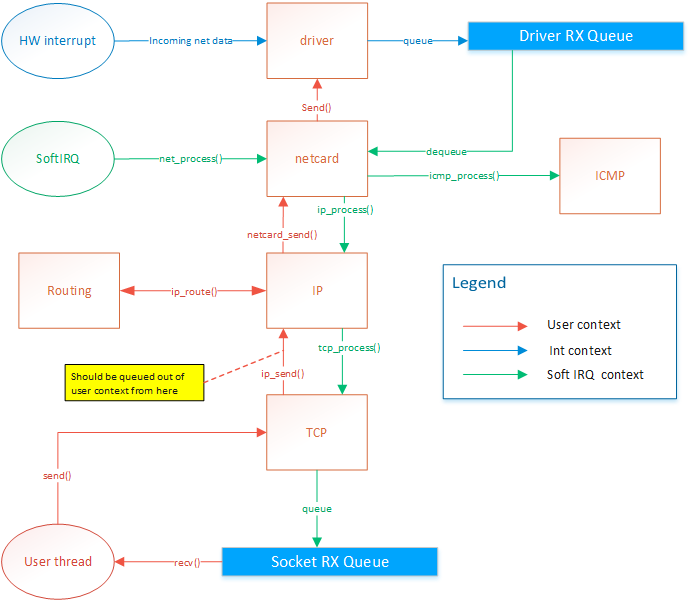
Network card drivers
The netcard abstration layer is contained in netcard.c.
When the OS boots, net_init() is called. This function
iterates through the PCI bus's devices to find all devices
that match one of the OS's netcard drivers. For each netcard
found, a struct NetworkCard is instanciated. The structure
contains several function pointers that are initialized with
the matching driver's functions. For example, NetworkCard::receive
would be set to &rtl8139_receive if the netcard was a rtl8139.
Each of these NetworkCard instances will be refered to as the
"netcard implementation"
Only the rtl8139 driver is implemented right now. You can view the source code
I have posted a while ago in Realtek 8139 network card driver
When a netcard IRQ occurs, a softIRQ is scheduled. (I know, softIRQ is a linux concept. But I actually
thought about it before knowing it existed in linux. I didn't have a name for it so I found that Linux
had a great name so I stole it. But it doesn't really work like linux's softIRQ. Linux has a way better
way of doing it than my OS). When the softIRQ handler is invoked, it calls net_process(). net_process() iterates through all netcard that was discovered during boot.
It then checks if data is available and forwards the the data
up to the TCP/IP stack if the data is an IP packet, or to the
ICMP stack if the packet is of the ICMP type.
TCP/IP stack
Receiving data
The ICMP handler responds immediately to ping requests. Therefore
the ICMP response is sent from the softIRQ thread. This allows
consistent RTT. The IP handler forwards the message to the TCP or
UDP handlers. The UDP handler is not implemented yet. The TCP
handler forwards segments to active sockets by finding the socket
listening to the port and ip of the message. This is done by by
finding the socket instance within a hash list. The message is added
in the socket's queue. The user thread is then responsible for
dequeuing those messages.
Sending data
The netcard abstraction's net_send() function locks
the netcard implementation's send spinlock. This way, only
one thread can send to one given netcard at the same time.
net_send() takes an interface index as destination parameter.
ip_send takes an ip address as destination parameter. ip_send
invokes ip_routing_route() to determine on what netcard
to send the message based the destination address.
net_send() will send 1 frame of maximum MTU size. It returns 0 if sending failed
or size of frame if sending suceeded. Frames are guaranteed to be sent in full or
not at all but never partly.
ip_send() will send a packet of maximum 65536 bytes. It will do ip fragmentation
in order to send frames of appropriate size.
tcp_send() will send 1 segment of maximum 64k. This means that the underlying
ip_send() can end up calling net_send several times.
Problem
There is actually a design flaw with tcp_send right now. Sending data on a socket
will end up in netcard_send being called from the user thread. The call is thus blocking.
Also, If net_send() returns 0, because of HW buffer overflow, then ip_send will return the
number of bytes sent. But tcp_send should not attempt to send the rest of the data
because the IP protocol expects the rest of the packet.
IP routing
IP routing is a whole subject itself. There are many algorithms and many ways to do this. It's actually the center of a very big industry.
Basically, when a packet needs to be sent out, we know destination IP to which we want to send. The OS needs to know out of with netcard
(if there are more than one) to send the packet and it also needs to know the source IP address to put in the packet. Normally, there
would be one IP per netcard. Linux allows you to setup multiple IP for one physical netcard, so this would be done by creating virtual netcards.
So the rule would still hold: 1 IP per netcard. My OS does not support virtual netcards, so only one IP per physical netcards.
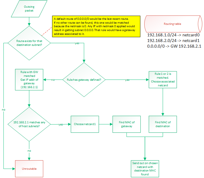
This is all done with a routing table. By default, the routing table will consist of an entry for each IP configured IP for the host.
Those route would be something like "anything within my own LAN must be forwarded out on my netcard". So if netcard0 has IP 192.168.1.88/24
and netcard1 has IP 192.168.2.25/24 then the routes would be:
- 192.168.1.0/24 -> netcard with IP 192.168.1.88 (netcard0)
- 192.168.2.0/24 -> netcard with IP 192.168.2.25 (netcard1)
A route can either say:
- if destination IP matches my subnet, then route out of interface X
- if destination IP matches my subnet, then route out to GW with IP address X
To match a rule, the rule's netmask is applied to the destination IP and the rule's IP. These masked IPs are subnets.
If both subnets match, then the rule matches. A rule of 0.0.0.0/0 would be a default route and would guarantee to always match.
It would be the last resort route.
Usually, routing out of an interface is done when we expect a device connected on that interface (through a switch probably)
to be able to recognize that destination IP. When routing to a GW IP, it is because we expect a specific device to know where
to find that destination IP. This would be a router. A default route would be configured like that. If an outgoing packet's destination
IP address matches the default route, it means it couldn't match any of the other routes. So we want to send that packet
to a gateway. We expect the gateway to be able to route the packet because our own routing table can't.
So the destination subnet is verified in order to find a route for that subnet. The subnet is the IP address logically AND'ed with
the netmask.
Then a route for the default gateway must be added. This will tell: "Anything not matched in the LAN IPs must be sent to this IP".
So something like: 0.0.0.0/24 -> 192.168.2.1. So if something needs to be sent to 192.168.5.6 then that route would be matched. The OS
would then compare the subnet (using the netmask) of that gateway with the IPs configured on the host. It would find that this IP
(of the gateway) is on the same LAN than 192.168.2.25 so netcard1 will be chosen as the outgoing netcard and the destination MAC
address of the gateway will be used. So it is clear that using a gateway that reside on a subnet that doesn't match any of the host's
IPs would be an invalid
configuration.
Frame forwarding
At the layer 2, devices don't know about IP addresses. They only know about MAC addresses. Only devices connected together on the same
layer 2 network (physically connected with switches) can talk to each other. When a packet is ready to be sent out, its MAC address might
not be known yet. The OS will discover it by sending an ARP request: "who has IP 192.168.2.1?". Then, that device will answer
"Me, and my MAC is xx:xx:xx:xx:xx:xx". So that destination MAC address will be used. When sending a packet to an external network, that is
behind a router, such as the example of 192.168.5.6 earlier, the destination MAC of the gateway will be used. So if we send a packet to a
device (by selecting its MAC as the destination) but the destination IP does not match that device's IP, it means we are expecting that
device to be able to do layer 3 routing. Such a device would generally be a router. But it could also be any workstation on the LAN.
Those workstations could be able to route. Linux does it.
Blocking operations
All socket operations such as connect, accept, send, receive and close are
non-blocking. This implies that the lower-level layer operations are non-blocking
also. There are some exceptions to this, but only because there are design flaws
that need to be addressed.
Problem
Upon connecting a socket, ARP discovery and DNS resolution might need to be
performed. DNS resolution will be left to the user to do. connect() will require an
IP address. Upon connect, the socket will be placed in "arp discovery" state. The MAC
address will be fetched from the cache or a discovery will be sent. Upon receiving an
ARP reply, or any other ARP cache entry addition, the stack will search through the
socket list for sockets that are waiting for that entry. The connection will then be
resumed. Once the an ARP entry is found for a socket, it will be saved in the socket
and reused for all remaining transmission.
Locking
At any time, only two threads can access the tcp/ip stack: The softIRQ thread,
for processing incomming frames, and the owner of the socket. If multiple
threads want to share socket usage, they will have to implement their own
locking mechanism. The tcp/ip stack will only guarantee thread safety between
the two threads mentioned above. Sockets should be used by one thread only in
a user application. Two different sockets can be used by two different threads
at the same time though.
net_send() locking
net_send() is used by the softIRQ context and user threads. Since
the softIRQ context has high priority, it means that if a thead
is preempted while it was holding the netcard's send spinlock, and
then the softIRQ attempts to request the lock, a deadlock might occur.
On uni-CPU systems, a deadlock would occur because the softIRQ will
never give CPU time to other threads until it has completed its work.
This could also happen on systems where the number of netcard is
greater than or equal to the number of CPUs.
To solve this problem, the spinlock will disable interrupts.
- Spinlock will prevent another CPU from accessing the send function
- The thread would not be preempted on the local CPU so there is no chances that a softIRQ would deadlock (since softIRQ are prioritized over that thread, it could continue to run and never give time to the thread to release the lock).
- On a single-CPU system, the interrupt cleared and spinlock would be redundant but would not cause a problem
Socket locking
No locking is currently done at the socket level. The following is a list
of problems that would arise, and the associated solution
Problem 1
- Make sure a thread does not delete its socket while softIRQ is using it.
- A thread might want to get the seqnumber while the softirq is modifying it.
- A thread might read in the receive queue while softIRQ is writing in it
Solution
??????
Problem 2
Make sure that only one consumer at a time can append/remove from the socket list.
Solution
The hash list is thread safe so it should already be handled correctly.
But more tests need to be done because there is a little more to it than
just accessing the hash list.
Problem 3
Socket backlog list might get accessed by softIRQ and owning thread
Solution
??????
Accepting incomming connections
A socket is created using create_socket(). Then the socket is placed in listening
mode with listen(). listen() will set the source ip/port of the socket as per
parameters of the function and destination ip/port to 0. A backlog buffer is created
with size=(sizeof(socket*)*backlogCount).
When a segment is processed by tcp_process (in softirq context), a socket will try
to be matched. If no socket is found then tcp_process() will try to find a listening
socket that uses the same source ip/port (matching the received segment's destination
fields) and with destination ip/port set to 0. if a socket is found, then we know
that this segment is for an incomming connection.
The listening socket will only process SYN segments and will ignore any other
segments. When processing a SYN segment, it will create a new socket with the same
source ip/port and with destination ip/port matching the source of the incomming
segment. The state will be set to CONNECTING. The new pending socket will be saved
in the listening socket's backlog. The new socket will stay in the backlog until it
gets picked up by accept(). accept() will then move the socket to the main list. The
socket created in the backlog is only temporary. accept() will create a new socket
instance based on that socket so that the new instance will reside in the accepting
process's heap.
When the accept function is called, it will go through the backlog of the listening
socket and will finish creating the socket. It will clone the socket and create the
receive buffer and send the syn/ack. The socket will stay in "CONNECTING" state until
it receives the ack of the syn/ack accept will move the socket from the backlog to
the main list.
Other articles about my OS
Process Context ID and the TLB
Thread management in my hobby OS
Enabling Multi-Processors in my hobby OS
Block caching and writeback
Memory Paging
Stack frame and the red zone (x86_64)
AVX/SSE and context switching
Realtek 8139 network card driver