OVERLAY NETWORKS WITH MY SDN CONTROLLER
2018-01-06

The code for this project is, again, available on github: https://github.com/pdumais/OpenflowController. I am not using any OF libraries, this is 100% home-made.
Intro
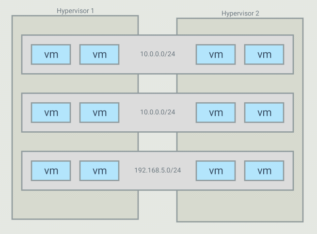
The objective with this project is to be able to create virtual networks
that span across several switches. For example, I have 5 VMs that run in
a 10.0.0.0/24 subnet but those VMs are on different hypervisors. I want my controller
to create an overlay network for those, and only those, VMs. It is possible
to have many overlays with the same addressing space because the switches
will only forward traffic between hosts part of the same overlay
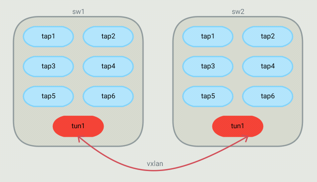
For such a topology, OVS bridges end up looking like this:
The controller
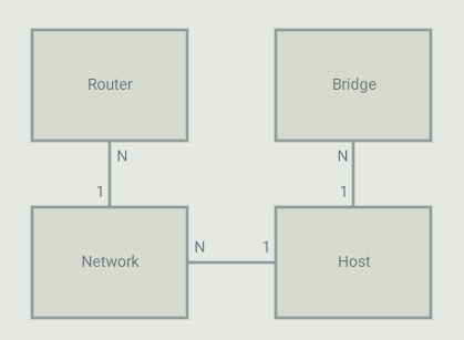
On the controller, I configure 4 types of objects: Bridges, Networks, Routers and Hosts.
A host is a VM or a container (or anything using a TAP interface in the OVS bridge).
Each host is part of a bridge. In general, you'd setup one bridge per hypervisor.
So because I define where bridges are (on which hypervisor they run), the controller
knows that 2 hosts run on different hypervisors and they should communicate through a tunnel.
Each host is part of a network. Those are virtual network that I define in the controller.
The controller will allow communication between hosts that are on the same virtual network.
A virtual network can span across many bridges. From the controller's point of view, all
the configuration is static. For each host, I define the bridge it is on, the port number
it is using, it's IP address and mac address. The mac,port,bridge could be given to
the controller by some kind of agent that would run on the HV but in my case, I have
just hardcoded those values. The IP address of the VM can be set to anything.
Flows
DHCP
Since I pre-configure the controller with the list of hosts that will attach to it with their MAC, IP
and networkID, gateway IP etc., the controller has all the information it needs to act as a DHCP server.
So the controller adds a flow, 1 for every host that is local to the hypervisor, to match the source MAC/port
and UDP port 67 with an action to send the packet to the controller. The controller then crafts a DHCP reply
packet and sends it back on the ingress port.
ARP
Again, since the controller has all information about the hosts, it is also capable of responding to ARP queries.
Flows are installed to intercept any ARP query and the controller will craft a response. If a host makes
an ARP query, that query will never be flooded (not even on the vxlan tunnel) and will never be seen by
anyone else than the controller. Technically, no hosts should ever receive ARP requests.
Table 0
Table 0 contains the flows to match ARP and DHCP requests. If a packet does not match any flow in Table 0,
a table-miss flow will send the packet to Table 1.
Table 1
Table 1 is about matching the source of a packet. For each host on the current bridge, a flow
that matches the in_port,src_mac,src_ip will be installed. The actions are to set the
virtual network ID in the tunnel_id metadata (will be used in Table 3) and then goto Table 2
Another flow that matches the tunnel in_port is installed with an action to goto Table 3.
That tunnel flow doesn't set the tunnel_id metadata because it was already set when
the packet came through the tunnel. The tunnel_id of a packet coming in from a VXLAN
tunnel is the VNI.
Table 2
Table 2 has flows that match dst_mac set to gateway addresses as defined in Router objects.
These flows are used for routing between virtual networks. If the dst_mac is not for
a virtual router, then a table-miss flow sends the packet to table 3.
Table 3
Table 3 is about forwarding to the correct host. When a packet enters Table 3, it is
guaranteed to have a tunnel_id (set as the virtual network ID).
Table 3 contains 1 flow for each host known across all virtual networks.
All flows match the tunnel_id,dst_mac,dst_ip. The action depends on if the host
is local or resides on another hypervisor. If it is local, then the action
is simply to forward to the port of that host. If it is remote, then 2 actions
are executed: Set-Field for remote tunnel endpoint IP and output to the tunnel
port. Note that since the tunnel_id is set (in table 1), the VXLAN packet created
by OVS will have that ID as the VNI. So when entering the other HV, a flow will
match that to the virtual network ID of the host.
So since the controller knows about all VMs and virtual networks, it is able to install
those flows that will make traffic between hosts part of the same virtual network possible,
even across hypervisors, thanks to VXLAN tunnels.
Example flows
Here is an example of the flows created on Hypervisor 1 from the above example setup
First, we see that in table 0, we intercept all ARP queries from all local hosts and send them to the controller.
The controller will respond if the target is a local or a remote host
 cookie=0x200000000000000, duration=20.254s, table=0, n_packets=0, n_bytes=0, priority=101,arp,in_port=3,dl_src=3e:d4:89:c5:d5:ec,arp_op=1 actions=CONTROLLER:65535
 cookie=0x200000000000000, duration=20.253s, table=0, n_packets=2, n_bytes=84, priority=101,arp,in_port=5,dl_src=8a:14:11:f1:3d:c9,arp_op=1 actions=CONTROLLER:65535
 cookie=0x200000000000000, duration=20.253s, table=0, n_packets=0, n_bytes=0, priority=101,arp,in_port=6,dl_src=8e:2b:b5:39:03:64,arp_op=1 actions=CONTROLLER:65535
 cookie=0x200000000000000, duration=20.252s, table=0, n_packets=0, n_bytes=0, priority=101,arp,in_port=4,dl_src=b2:5b:4e:49:85:59,arp_op=1 actions=CONTROLLER:65535
 cookie=0x200000000000000, duration=20.252s, table=0, n_packets=0, n_bytes=0, priority=101,arp,in_port=2,dl_src=ba:ce:a6:08:b6:67,arp_op=1 actions=CONTROLLER:65535
 cookie=0x200000000000000, duration=20.251s, table=0, n_packets=0, n_bytes=0, priority=101,arp,in_port=1,dl_src=da:1d:64:e8:e6:86,arp_op=1 actions=CONTROLLER:65535
Then, in table 0 still, we intercept DHCP requests.
The last flow is the table-miss flow that will make us jump to table 1
 cookie=0x100000000000000, duration=20.254s, table=0, n_packets=0, n_bytes=0, priority=100,udp,in_port=3,dl_src=3e:d4:89:c5:d5:ec,tp_dst=67 actions=CONTROLLER:65535
 cookie=0x100000000000000, duration=20.253s, table=0, n_packets=1, n_bytes=342, priority=100,udp,in_port=5,dl_src=8a:14:11:f1:3d:c9,tp_dst=67 actions=CONTROLLER:65535
 cookie=0x100000000000000, duration=20.253s, table=0, n_packets=0, n_bytes=0, priority=100,udp,in_port=6,dl_src=8e:2b:b5:39:03:64,tp_dst=67 actions=CONTROLLER:65535
 cookie=0x100000000000000, duration=20.252s, table=0, n_packets=0, n_bytes=0, priority=100,udp,in_port=4,dl_src=b2:5b:4e:49:85:59,tp_dst=67 actions=CONTROLLER:65535
 cookie=0x100000000000000, duration=20.252s, table=0, n_packets=0, n_bytes=0, priority=100,udp,in_port=2,dl_src=ba:ce:a6:08:b6:67,tp_dst=67 actions=CONTROLLER:65535
 cookie=0x100000000000000, duration=20.251s, table=0, n_packets=0, n_bytes=0, priority=100,udp,in_port=1,dl_src=da:1d:64:e8:e6:86,tp_dst=67 actions=CONTROLLER:65535

 cookie=0x8a22420000000000, duration=20.255s, table=0, n_packets=0, n_bytes=0, priority=0 actions=goto_table:1
Now in table 1, we match the source of all known local hosts and set the tun_id field (VNI), which is a way for us to tag the packet with its
network ID. The last flow matches the in_port 65279, which is the tunnel port. It will make us jump to table 2. The tun_id is already
set for all packets comming in from the tunnel
 cookie=0x200000000000000, duration=20.254s, table=1, n_packets=0, n_bytes=0, priority=300,ip,in_port=3,dl_src=3e:d4:89:c5:d5:ec,nw_src=10.0.0.1 actions=set_field:0x2->tun_id,goto_table:2
 cookie=0x200000000000000, duration=20.253s, table=1, n_packets=0, n_bytes=0, priority=300,ip,in_port=5,dl_src=8a:14:11:f1:3d:c9,nw_src=192.168.5.1 actions=set_field:0x3->tun_id,goto_table:2
 cookie=0x200000000000000, duration=20.253s, table=1, n_packets=0, n_bytes=0, priority=300,ip,in_port=6,dl_src=8e:2b:b5:39:03:64,nw_src=192.168.5.2 actions=set_field:0x3->tun_id,goto_table:2
 cookie=0x200000000000000, duration=20.252s, table=1, n_packets=0, n_bytes=0, priority=300,ip,in_port=4,dl_src=b2:5b:4e:49:85:59,nw_src=10.0.0.2 actions=set_field:0x2->tun_id,goto_table:2
 cookie=0x200000000000000, duration=20.252s, table=1, n_packets=0, n_bytes=0, priority=300,ip,in_port=2,dl_src=ba:ce:a6:08:b6:67,nw_src=10.0.0.2 actions=set_field:0x1->tun_id,goto_table:2
 cookie=0x200000000000000, duration=20.251s, table=1, n_packets=0, n_bytes=0, priority=300,ip,in_port=1,dl_src=da:1d:64:e8:e6:86,nw_src=10.0.0.1 actions=set_field:0x1->tun_id,goto_table:2
 cookie=0x0, duration=20.255s, table=1, n_packets=0, n_bytes=0, priority=200,in_port=65279 actions=goto_table:3
In table 3, we match the tun_id and the destination and forward out to the appropriate port if the destination host is local
 cookie=0x0, duration=20.254s, table=3, n_packets=0, n_bytes=0, priority=400,ip,dl_dst=52:21:f7:11:a6:10,nw_dst=192.168.5.4 actions=set_field:0x3->tun_id,set_field:192.168.1.2->tun_dst,output:65279
 cookie=0x0, duration=20.254s, table=3, n_packets=0, n_bytes=0, priority=400,ip,dl_dst=5e:9f:86:77:6e:87,nw_dst=192.168.5.3 actions=set_field:0x3->tun_id,set_field:192.168.1.2->tun_dst,output:65279
 cookie=0x0, duration=20.254s, table=3, n_packets=0, n_bytes=0, priority=400,ip,dl_dst=74:4b:c6:95:18:73,nw_dst=10.0.0.4 actions=set_field:0x2->tun_id,set_field:192.168.1.2->tun_dst,output:65279
 cookie=0x0, duration=20.254s, table=3, n_packets=0, n_bytes=0, priority=400,ip,dl_dst=7e:cc:09:63:aa:6f,nw_dst=10.0.0.4 actions=set_field:0x1->tun_id,set_field:192.168.1.2->tun_dst,output:65279
 cookie=0x0, duration=20.253s, table=3, n_packets=0, n_bytes=0, priority=400,ip,dl_dst=86:95:72:30:f5:ac,nw_dst=10.0.0.5 actions=set_field:0x2->tun_id,set_field:192.168.1.2->tun_dst,output:65279
 cookie=0x0, duration=20.251s, table=3, n_packets=0, n_bytes=0, priority=400,ip,dl_dst=ea:3d:e4:bc:b6:9f,nw_dst=10.0.0.5 actions=set_field:0x1->tun_id,set_field:192.168.1.2->tun_dst,output:65279
These last flows, in Table 3 again, match the destination of all remote hosts and forwards the packet out of the tunnel port
after having set the tunnel destination address (address of the HV running that host)
 cookie=0x200000000000000, duration=20.254s, table=3, n_packets=0, n_bytes=0, priority=300,ip,tun_id=0x2,dl_dst=3e:d4:89:c5:d5:ec,nw_dst=10.0.0.1 actions=output:3
 cookie=0x200000000000000, duration=20.253s, table=3, n_packets=0, n_bytes=0, priority=300,ip,tun_id=0x3,dl_dst=8a:14:11:f1:3d:c9,nw_dst=192.168.5.1 actions=output:5
 cookie=0x200000000000000, duration=20.253s, table=3, n_packets=0, n_bytes=0, priority=300,ip,tun_id=0x3,dl_dst=8e:2b:b5:39:03:64,nw_dst=192.168.5.2 actions=output:6
 cookie=0x200000000000000, duration=20.252s, table=3, n_packets=0, n_bytes=0, priority=300,ip,tun_id=0x2,dl_dst=b2:5b:4e:49:85:59,nw_dst=10.0.0.2 actions=output:4
 cookie=0x200000000000000, duration=20.252s, table=3, n_packets=0, n_bytes=0, priority=300,ip,tun_id=0x1,dl_dst=ba:ce:a6:08:b6:67,nw_dst=10.0.0.2 actions=output:2
 cookie=0x200000000000000, duration=20.251s, table=3, n_packets=0, n_bytes=0, priority=300,ip,tun_id=0x1,dl_dst=da:1d:64:e8:e6:86,nw_dst=10.0.0.1 actions=output:1
VXLAN tunnels
I had a hard understanding how to create the tunnels at first.
I know that with OVS, we can create VXLAN tunnel ports and we just need
to forward traffic on those ports. But this requires configuring (N-1) tunnel ports
on each hypervisors if we have a total of N hypervisors. So instead I found that
there is an openflow extension (so not part of the official spec) that allows
to set the destination of the tunnel dynamically with a flow. This is done with
a "set-field" action, with a OXM class of 0x001 and field ID 32 (this is a Nicira extension).
Then you only need to create 1 tunnel port per hypervisor like this:
ovs-vsctl add-port sw1 vtun1 -- set interface vtun1 type=vxlan options:remote_ip=flow options:key=flow
Using "flow" as the remote_ip allows us to set the destination IP using flows. And setting key=flow allows us to set the VNI with flows.
Routing
Routing is a very simple process. When a host sends a packet to another host,
on another network, it simply uses the mac address of the gateway as the destination
mac. So from the switch's point of view, it's just a matter of detecting that "special"
mac address and allowing to forward on a port that is on a different virtual network.
In my controller, this done by configuring
a Router object in the controller and adding networks it. The router
will allow communication between networks associated to it. When a host
needs to send traffic to another network, it needs to go through a gateway.
in the configuration shown above, we can see that an IP has been assigned as
the gateway ip in each network. The controller will respond to arp queries
for those gw IP with the mac adress of the virtual router that those networks are
associated to. So hosts will be sending their inter-network traffic using the
virtual router's mac as the destination mac.
So the controller can install flows to match traffic with that mac and
the dst_ip (with a mask) to change the network id on that packet. the packet
can then be sent to table 3 for proper port forwarding.
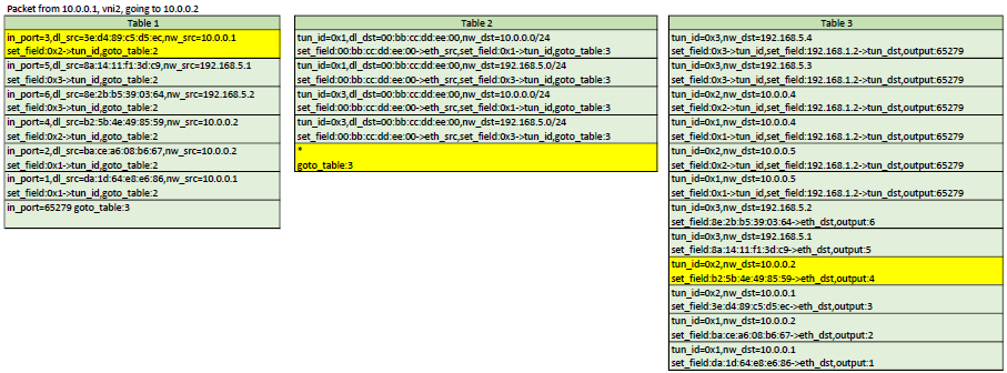
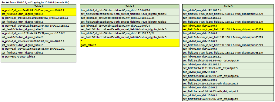
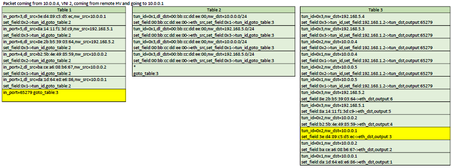
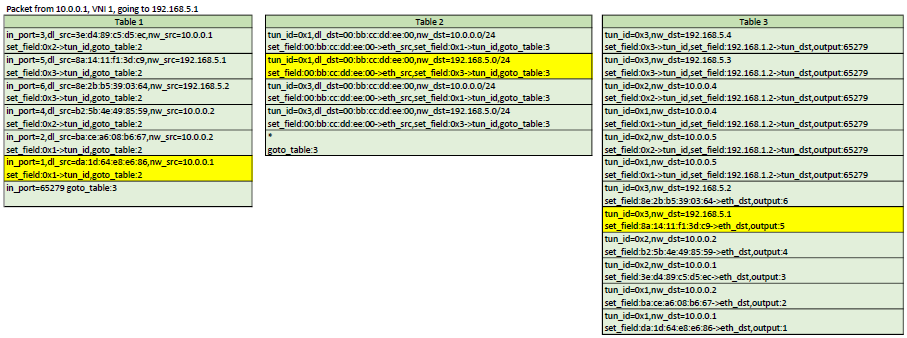
Example flows
Here is a representation of table 1,2,3. In each scenario, the yellow flows are the ones
that would be matched
Configuration
Like I've mentionned above, right now, the configuration is very static. We have
to pre-configure the controller and tell it exactly where (on which HV) each VMs runs,
the port number in the OVS they are attached to and their MAC address. Although the controller
could deduct some of that information, I prefer to tell it exactly what I am expecting so
I can exercise better control over my network.
    u8 mac1[] = {0xda,0x1d,0x64,0xe8,0xe6,0x86};
    u8 mac2[] = {0xba,0xce,0xa6,0x08,0xb6,0x67};
    u8 mac3[] = {0x3e,0xd4,0x89,0xc5,0xd5,0xec};
    u8 mac4[] = {0xb2,0x5b,0x4e,0x49,0x85,0x59};
    u8 mac5[] = {0x8a,0x14,0x11,0xf1,0x3d,0xc9};
    u8 mac6[] = {0x8e,0x2b,0xb5,0x39,0x03,0x64};
    u8 mac7[] = {0x7e,0xcc,0x09,0x63,0xaa,0x6f};
    u8 mac8[] = {0xea,0x3d,0xe4,0xbc,0xb6,0x9f};
    u8 mac9[] = {0x74,0x4b,0xc6,0x95,0x18,0x73};
    u8 mac10[] = {0x86,0x95,0x72,0x30,0xf5,0xac};
    u8 mac11[] = {0x5e,0x9f,0x86,0x77,0x6e,0x87};
    u8 mac12[] = {0x52,0x21,0xf7,0x11,0xa6,0x10};

    // We define the hypervisor with their datapath ID and management IP
    this->addBridge(0x32d1f6ddc94f,"192.168.1.216");
    this->addBridge(0x4e7879903e4c,"192.168.1.2");

    // Define overlay networks: id, net, mask, GW ip, DNS server
    this->addNetwork(1,"10.0.0.0","255.255.255.0","10.0.0.254","10.0.0.250");
    this->addNetwork(2,"10.0.0.0","255.255.255.0","10.0.0.253","10.0.0.249");
    this->addNetwork(3,"192.168.5.0","255.255.255.0","192.168.5.253","192.168.5.249");

    // We will create 1 router to be able to route between network 1 and 3
    // We can route between 1 and 2 because they have the same network address
    this->addRouter(0x00bbccddee00);
    this->addNetworkToRouter(this->routers[0x00bbccddee00],this->networks[1]);
    this->addNetworkToRouter(this->routers[0x00bbccddee00],this->networks[2]);

    // Define the hosts: mac, network ID, port, IP, hypervisor ID
    this->addHost(extractMacAddress((u8*)mac1),1,1,"10.0.0.1",0x32d1f6ddc94f);
    this->addHost(extractMacAddress((u8*)mac2),1,2,"10.0.0.2",0x32d1f6ddc94f);
    this->addHost(extractMacAddress((u8*)mac3),2,3,"10.0.0.1",0x32d1f6ddc94f);
    this->addHost(extractMacAddress((u8*)mac4),2,4,"10.0.0.2",0x32d1f6ddc94f);
    this->addHost(extractMacAddress((u8*)mac5),3,5,"192.168.5.1",0x32d1f6ddc94f);
    this->addHost(extractMacAddress((u8*)mac6),3,6,"192.168.5.2",0x32d1f6ddc94f);
    this->addHost(extractMacAddress((u8*)mac7),1,1,"10.0.0.4",0x4e7879903e4c);
    this->addHost(extractMacAddress((u8*)mac8),1,2,"10.0.0.5",0x4e7879903e4c);
    this->addHost(extractMacAddress((u8*)mac9),2,4,"10.0.0.4",0x4e7879903e4c);
    this->addHost(extractMacAddress((u8*)mac10),2,5,"10.0.0.5",0x4e7879903e4c);
    this->addHost(extractMacAddress((u8*)mac11),3,6,"192.168.5.3",0x4e7879903e4c);
    this->addHost(extractMacAddress((u8*)mac12),3,7,"192.168.5.4",0x4e7879903e4c);
So right now, if I create a VM, I need to tell the controller about that new VM and provide the following information:
- MAC address
- Network ID (that will be used as the VNI)
- Hypervisor where the VM runs
- IP Address I want assigned for the VM
- Port number on the OVS bridge
Note that the chosen IP address can be configured manually on the VM, but if
choosing DHCP, the controller will intercept the request and assign that IP.
So I would need a tool to do this for me instead of doing that step manually
after creating a VM. So what could be done next is to create an orchestrator that allows me to spawn VMs on any
of the HV (transparently maybe?). At the time of creation, I would need to specify in
which network I want my VM to be part of. Then the orchestrator would choose a HV,
choose a and IP from the network that was selected and spawn the VM. After spawning
the VM, the orchestrator would know the MAC address and the OVS port number that
the VM was started with. At that point, the orchestrator has all the information
needed to tell the controller how to establish proper networking for that new VM.
What next?
I guess that a cool feature I could do next would be to have a way for those virtual networks to access an external network such as the internet. This would involve NAT and a way route to the underlay. I'll have to think about that one.
SIMPLE LEARNING SWITCH WITH OPENFLOW
2017-12-16
Introduction
I recently wanted to learn more about Openflow so I decided to write a controller that acts as
a simple L2 learning switch. The controller is written in c++. I couldn't find a good c++ library
for openflow so I ended up writing my own from scratch. The openflow code is far from being spec1.3-compliant
because it is missing a lot of things, but it does enough to accomplish my goals. The code for the
controller, including the Openflow code, is available on github. https://github.com/pdumais/OpenflowController
Openflow Controller
The general idea behind my implementation of the openflow controller, is to program the switch
as the controller discovers the network. The controller is made aware of the vlans on which ports
should belong to through a configuration file.
When the switch connects to the controller, the controller will delete all flows in tables 0,1,2.
It will then install a table-miss rule (match all, priority 0) in table 0 and 1 to send packets
the controller. table 2 will stay empty; the default behaviour of this will be to drop packets.
So at this point, any packets comming in on the switch will trigger a table-miss and be sent to
the controller. The controller will then make decisions on how the packet should be forwarded
based on the port type (access or trunk) and vlan. Whenever a packet gets sent to the
controller, this is done in a PacketIn message. The controller then send a PacketOut message
to tell the switch on which port(s) to forward that packet and to maybe add/delete a vlan tag.
In order to avoid having to do this processing everytime, the controller also adds a flow
on the switch with a specific match criteria and a set of action so that the logic
of the packetOut can be applied by the switch automatically the next time instead of sending
the packet to the controller.
Learning Switch
Many examples of a learning switch I saw were a bit naive. For example, those implementation would
fail if more than one host would be connected behind a port (for example, another switch could be
connected on that port). So my implementation is an attempt to be a bit more robust.
My learning switch uses two tables because there are two decisions that need to be taken
eveytime a packet comes in: 1) Should the controller learn about that mac/in_port? 2) What
port needs to be used to forward the packet?
When the first packet will be sent to the switch, it will be sent to the controller, because there
are only table-miss rules defined. The controller will learn the src_mac/in_port of that packet
and install a rule in table 0 to match that src_mac/in_port and forward to table 1. The next time
the same host sends a packet, it will not hit the table-miss rule in table 0 and will be forwarded
to table 1. After adding that rule, the contoller will look at the dst_mac of the packet
and will not have an entry in its FIB so it will send a PacketOut to the switch with a flood
action (if vlans are used, this is a bit different).
As packets come in, table0 will get populated with entries to avoid sending already
learned sources to the controller. But when hitting table 1, packets will hit the table-miss
rule. So the packets will be sent to the controller. The controller will look at the dst_mac and
decide to flood (as described above) or not. If the dst_mac was found in the FIB (because
it was previously learned through another packet's table-miss on table 0), the a packetOut
is sent with only the port found in the FIB. Also, a rule will be installed in table 1
to match the dst_mac.
Example: At time 0, the bridge only has table-miss flows installed, so anything going in the switch
will hit that and be sent to the controller.
- first packet sent from A on port 1, destined to B, on port 2
- table0-miss
- learn(A is on port 1)
- installRule(in t0, if from A and on port 1, goto t1)
- check destination
- not found!
- PacketOut(flood)
- Then B responds on port 2
- table-0-miss
- learn(B is on port 2)
- installRule(in t0, if from B and on port 2, goto t1)
- check destination
- Found! A is on port 1.
- PacketOut(1)
- installRule(in t1, if for A, forward to 1)
- Then A sends something else to B
- table-0 Pass, jump to t1
- table1-miss (no rule for destination B)
- check destination
- Found! B is on port 2.
- PacketOut(2)
- installRule(in t1, if for B, forward to 2)
- And B replies to A again
- table-0 Pass, jump to t1
- table-1 Pass, forward according to rule.
Vlans
When vlans are involved, things changes a bit. The switch is configured
with a set of port in different vlans. The switch determines the vlan
that the incomming packet belongs to by looking at the vlanID in the packet if
it came in through a port that is configured with a "trunk" personality. If
the traffic is untagged and came in on a trunk, then a "default vlan" config
is also available. Note that these configs are set on my controller when I define
the virtual topology of the switch, and not on openvswitch itself. If the port
is an access port, then traffic is assumed to be for the vlan configured on the port.
The controller maintains a forwarding table on a per-vlan basis. So it would be
technically possible to have the same MAC twice but on different vlans.
Flooding then happen only on ports part of the same vlan. Also, when flooding
out of trunk ports, a vlan tag must be added. This is all doable with flows.
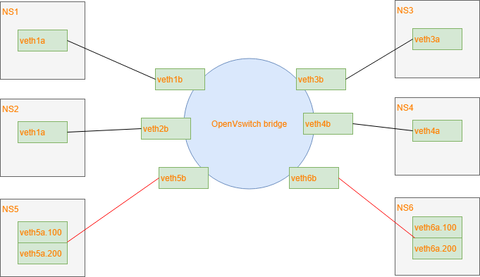
Test network
This is the test network I am using:
I am using veth pairs with 1 end in the bridge and the other end in its own network
namespace. This is easier than to create 6 VMs.
The controller is configured to recognize interfaces 1,2 as access ports for vlan 100.
Interfaces 3,4 as access ports for vlan 200 and interfaces 5,6 as trunk ports for both vlans.
To better understand what the controller does, here is a series of openflow rules installed
after the controller has seen some packets go through
After a packet (ARP query) was sent from port1, we learned the mac, so we can skip table 0
table=0, n_packets=6, n_bytes=532, priority=100,in_port=1,dl_src=da:1d:64:e8:e6:86 actions=goto_table:1
After getting the arp response, we learned the address so we can skip table 0 next time
table=0, n_packets=5, n_bytes=434, priority=100,in_port=4,dl_src=b2:5b:4e:49:85:59 actions=goto_table:1
After a packet came out of trunk port5 with vlan tag 100, we can skip table0 because we learned it.
Notice how we match against the vlan tag here.
table=0, n_packets=6, n_bytes=556, priority=100,in_port=5,dl_vlan=100,dl_src=5a:54:c5:e5:6b:27 actions=goto_table:1
Same as above but for vlan 200
table=0, n_packets=5, n_bytes=454, priority=100,in_port=5,dl_vlan=200,dl_src=5a:54:c5:e5:6b:27 actions=goto_table:1
This is the table-miss flow. If none of the above rules match a packet in table0, we send it to the controller.
This would happen because we need to learn the source MAC
table=0, n_packets=4, n_bytes=288, priority=0 actions=CONTROLLER:65535
At this point, these are the rules for table1. If a packet makes it to here, it means that the source_port/mac
was already learned before and we need to check for a destination mac flow to forward it to the correct port.
When trying to send a packet, it triggered a table miss but the controller found that the destination mac
was in it's FIB. So it installed a flow matching the source port,vlanID and destination. The actions
here are to pop the vlan tag because in_port 5 is a trunk and we need to send the packet to port 1, which is an access port.
table=1, n_packets=6, n_bytes=556, priority=100,in_port=5,dl_vlan=100,dl_dst=da:1d:64:e8:e6:86 actions=pop_vlan,output:1
Same as above, different values
table=1, n_packets=4, n_bytes=352, priority=100,in_port=5,dl_vlan=200,dl_dst=b2:5b:4e:49:85:59 actions=pop_vlan,output:4
That flow pushes a vlan tag because the destination mac was previously found behind a trunk port
table=1, n_packets=6, n_bytes=532, priority=100,in_port=1,dl_dst=5a:54:c5:e5:6b:27 actions=push_vlan:0x8100,set_field:4196->vlan_vid,output:5
Same as above, different values
table=1, n_packets=5, n_bytes=434, priority=100,in_port=4,dl_dst=5a:54:c5:e5:6b:27 actions=push_vlan:0x8100,set_field:4296->vlan_vid,output:5
This is the table-miss flow. If none of the above rules match a packet in table1, we send it to the controller.
This would happen because there are no flows installed to forward the destination MAC to the correct port.
The controller will either have that destination in its FIB and will install a flow in table 1 for next time
Or it will flood on all ports of the same VLAN if the destination is not in the FIB.
table=1, n_packets=1, n_bytes=102, priority=0 actions=CONTROLLER:65535
Final thoughts
There are many other things that should be considered here by that I haven't implemented.
For example, if port is removed from the switch or if the port goes down, flows that
forwards to that port should be removed, and flows that match that incoming port should
also be removed. Broadcast flows should be modified. And if changing the vlan config
on a port, within the controller configuration, flows also need to be removed/modified.
INSTALLING KUBERNETES MANUALLY
2017-09-13
The procedure described here applies to centos but the same recipe can obviously be adapted for other distritions with some
minor tweaks.
I am deploying a 3 nodes cluster and all servers are master/nodes at the same time. This is not recommended by
the k8s team but for a lab environment it is perfectly fine. If you understand this procedure well, then you will find
that deploying nodes and masters separately can be just as easy. Let's assume I have 3 servers with IPs 192.168.1.100,192.168.1.101
and 192.168.1.102.
System preparation
First thing we need to do is disable selinux, disable the firewall, NetworkManager and setup a yum repo.
This is probably a bad idea, but then again, it makes things easier in a lab environment.
systemctl disable NetworkManager
systemctl stop NetworkManager
systemctl disable firewalld
systemctl stop firewalld
setenforce 0
sed -i "s/^SELINUX=.*/SELINUX=disabled/g' /etc/selinux/config
cat >> /etc/yum.repos.d/virt7-docker-common-release.repo << EOF
[virt7-docker-common-release]
name=virt7-docker-common-release
baseurl=http://cbs.centos.org/repos/virt7-docker-common-release/x86_64/os/
gpgcheck=0
EOF
If you are behind a corporate proxy, also add this line to that last repo file: proxy=http://yourproxy_address
Install docker
yum install -y docker
systemctl enable docker
systemctl start docker
If you are behind a corporate proxy, add this line to /etc/sysconfig/docker: HTTP_PROXY=http://yourproxy_address
and then restart docker
Install etcd
etcd should be installed on all masters. You actually have to install etcd on the same server where the k8s binaries
will be found, but you should definitely install several instances of it and cluster them. Some people also
suggest to install at least one instance somewhere in the cloud. This is because etcd will store all the persistant
admin stuff that k8s needs. So it would be painful to lose that data. Bringing back (or adding) a k8s node is very easy
and transparent as long as your etcd cluster is intact.
yum install -y etcd
cat >> /etc/etcd/etcd.conf << EOF
ETCD_INITIAL_CLUSTER="k1=http://192.168.1.100:2380,k2=http://192.168.1.101:2380,k3=http://192.168.1.102:2380"
ETCD_INITIAL_CLUSTER_STATE="new"
ETCD_INITIAL_CLUSTER_TOKEN="awesome-etcd-cluster"
ETCD_INITIAL_ADVERTISE_PEER_URLS="http://192.168.1.100:2380"
ETCD_DATA_DIR="/var/lib/etcd/default.etcd"
ETCD_LISTEN_PEER_URLS="http://192.168.1.100:2380"
ETCD_LISTEN_CLIENT_URLS="http://0.0.0.0:2379"
ETCD_ADVERTISE_CLIENT_URLS="http://192.168.1.100:2379"
ETCD_NAME="k1"
EOF
systemctl enable etcd
systemctl start etcd
The ETCD_INITIAL_CLUSTER line should list all the hosts where etcd will be running. The other lines where you see 192.168.1.100
should be modified to match the IP address of the server you are currently installing etcd on. and ETCD_NAME should also match
the server you are installing on (see the first line where these names are used). The ETCD_NAME can be any arbitrary name (as long
as you properly match them in ETCD_INITIAL_CLUSTER) but most people try to use the server's hostname.
After having installed etcd on all your servers, wait for the cluster to be up checking the output of "etcdctl cluster-health"
Make sure the cluster is up and healthy before continuing.
Now add some info about k8s in etcd
etcdctl mkdir /kube-centos/network
etcdctl mk /kube-centos/network/config "{ \"Network\": \"172.30.0.0/16\", \"SubnetLen\": 24, \"Backend\": {\"Type\": \"vxlan\" } }"
Install Flannel
Your k8s cluster will need an overlay network so that all pods appear to be on the same layer 2 segment. This is nice because even though
you cluster runs on different servers, each pod will be able to talk to each other using a virtual network that sits on top of your real
network and will span accross all k8s nodes. It's basically a virtual distributed switch, just like openvswitch does. Flannel is
one such driver that enables that for kubernetes. It is the most basic overly driver and works just fine. For more advanced stuff, Nuage is
an option and there are many other options. If you are new to this (like I was), then this is the SDN stuff that all the cool kids
are talking about.
yum install -y flannel
cat >> /etc/sysconfig/flanneld << EOF
FLANNEL_ETCD_ENDPOINTS="http://192.168.1.100:2379,http://192.168.1.101:2379,http://192.168.1.102:2379"
FLANNEL_ETCD_PREFIX="/kube-centos/network"
EOF
systemctl enable flanneld
systemctl start flanneld
Install Kubernetes
So far, we have just installed all the stuff that k8s requires. Now we get to the part where we actually install Kubernetes.
So to resume, we have installed:
- Docker: This is what will actually run the containers
- Etcd: This is the database that k8s and flannel uses to store admin data
- Flannel: The overlay network
Before we continue, let's create a user and some folders
groupadd kube
useradd -g kube -s /sbin/nologin kube
mkdir -p /var/run/kubernetes
chown root:kube /var/run/kubernetes
chmod 770 /var/run/kubernetes
mkdir /etc/kubernetes
mkdir /var/lib/kubelet
Kubernetes can be downloaded as a binary package from github. What I really like about these binaries is that they are simple standalone
applications. You don't need to install a RPM and a whole bunch of libraries. Simply copy the executable and run it. You will need a total
of 6 process to run. So the first thing to do is to unpack the binaries. Download the version you want from
https://github.com/kubernetes/kubernetes/releases
tar -zxf kubernetes.tar.gz
cd kubernetes
cluster/get-kube-binaries.sh
cd server
tar -zxf kubernetes-server-linux-amd64.tar.gz
cp kube-apiserver /usr/bin
cp kube-controller-manager /usr/bin
cp kubectl /usr/bin
cp kubelet /usr/bin
cp kube-proxy /usr/bin
cp kube-scheduler /usr/bin
chmod 554 /usr/bin/kube*
Each of the daemons can simply be started from the CLI with a whole bunch of command line arguments, you don't even need any
configuration files. This is beautiful because it is so easy.
So technically, you could just do:
kube-apiserver  &
kube-controller-manager  &
kubelet  &
kube-proxy  &
kube-scheduler  &
And that's it, kubernetes is running. Simple. But let's get systemd to manage those process. If you are not using systemd (slackware?) then
you can setup a bunch of rc scripts to launch those. But for this example, let's create some systemd unit files that will launch this for us.
#/usr/lib/systemd/system/kube-apiserver.service
[Unit]
Description=Kubernetes API Server
Documentation=https://github.com/GoogleCloudPlatform/kubernetes
After=network.target
After=etcd.service

[Service]
EnvironmentFile=-/etc/kubernetes/config
EnvironmentFile=-/etc/kubernetes/apiserver
User=kube
ExecStart=/usr/bin/kube-apiserver \
        $KUBE_LOGTOSTDERR \
        $KUBE_LOG_LEVEL \
        $KUBE_ETCD_SERVERS \
        $KUBE_API_ADDRESS \
        $KUBE_API_PORT \
        $KUBELET_PORT \
        $KUBE_ALLOW_PRIV \
        $KUBE_SERVICE_ADDRESSES \
        $KUBE_ADMISSION_CONTROL \
        $KUBE_API_ARGS
Restart=on-failure
Type=notify
LimitNOFILE=65536

[Install]
WantedBy=multi-user.target
#/usr/lib/systemd/system/kube-controller-manager.service
[Unit]
Description=Kubernetes Controller Manager
Documentation=https://github.com/GoogleCloudPlatform/kubernetes

[Service]
EnvironmentFile=-/etc/kubernetes/config
EnvironmentFile=-/etc/kubernetes/controller-manager
User=kube
ExecStart=/usr/bin/kube-controller-manager \
        $KUBE_LOGTOSTDERR \
        $KUBE_LOG_LEVEL \
        $KUBE_MASTER \
        $KUBE_CONTROLLER_MANAGER_ARGS
Restart=on-failure
LimitNOFILE=65536

[Install]
WantedBy=multi-user.target
#/usr/lib/systemd/system/kubelet.service
[Unit]
Description=Kubernetes Kubelet Server
Documentation=https://github.com/GoogleCloudPlatform/kubernetes
After=docker.service
Requires=docker.service

[Service]
WorkingDirectory=/var/lib/kubelet
EnvironmentFile=-/etc/kubernetes/config
EnvironmentFile=-/etc/kubernetes/kubelet
ExecStart=/usr/bin/kubelet \
        $KUBE_LOGTOSTDERR \
        $KUBE_LOG_LEVEL \
        $KUBELET_API_SERVER \
        $KUBELET_ADDRESS \
        $KUBELET_PORT \
        $KUBELET_HOSTNAME \
        $KUBE_ALLOW_PRIV \
        $KUBELET_POD_INFRA_CONTAINER \
        $KUBELET_ARGS
Restart=on-failure

[Install]
WantedBy=multi-user.target
#/usr/lib/systemd/system/kube-proxy.service
[Unit]
Description=Kubernetes Kube-Proxy Server
Documentation=https://github.com/GoogleCloudPlatform/kubernetes
After=network.target

[Service]
EnvironmentFile=-/etc/kubernetes/config
EnvironmentFile=-/etc/kubernetes/proxy
ExecStart=/usr/bin/kube-proxy \
        $KUBE_LOGTOSTDERR \
        $KUBE_LOG_LEVEL \
        $KUBE_MASTER \
        $KUBE_PROXY_ARGS
Restart=on-failure
LimitNOFILE=65536

[Install]
WantedBy=multi-user.target
#/usr/lib/systemd/system/kube-scheduler.service
[Unit]
Description=Kubernetes Scheduler Plugin
Documentation=https://github.com/GoogleCloudPlatform/kubernetes

[Service]
EnvironmentFile=-/etc/kubernetes/config
EnvironmentFile=-/etc/kubernetes/scheduler
User=kube
ExecStart=/usr/bin/kube-scheduler \
        $KUBE_LOGTOSTDERR \
        $KUBE_LOG_LEVEL \
        $KUBE_MASTER \
        $KUBE_SCHEDULER_ARGS
Restart=on-failure
LimitNOFILE=65536

[Install]
WantedBy=multi-user.target
Note how I did not hard code all command line arguments in the systemd unit files. Instead I will store them in separate environment files
under /etc/kubernetes. So earlier I was praising about how nice it was to just be able to launch the processes on the command line with not
extra config files or no service files but here I am create service files and config files. I know... I just like the fact that I can
customize it any way I want. So here are the config files needed. But as I said, you could just write one bash script that invokes
all those 5 process with all their command line arguments and you would have zero config file and no need for systemd. just 5 binaries
that you copied on your server.
#/etc/kubernetes/config
KUBE_ETCD_SERVERS="--etcd-servers=k1=http://192.168.1.100:2379,k2=http://192.168.1.101:2379,k3=http://192.168.1.102:2379"
KUBE_LOGTOSTDERR="--logtostderr=true"
KUBE_LOG_LEVEL="--v=0"
KUBE_ALLOW_PRIV="--allow-privileged=false"
KUBE_MASTER="--master=http://127.0.0.1:8080"
KUBE_SCHEDULER_ARGS="--leader-elect=true"
KUBE_API_ARGS="--leader-elect=true"
#/etc/kubernetes/apiserver
KUBE_API_ADDRESS="--insecure-bind-address=0.0.0.0"
KUBE_ETCD_SERVERS="--etcd-servers=http://127.0.0.1:2379"
KUBE_SERVICE_ADDRESSES="--service-cluster-ip-range=10.254.0.0/16"
KUBE_ADMISSION_CONTROL="--admission-control=AlwaysAdmit"
KUBE_API_ARGS=""
#/etc/kubernetes/controller-manager
KUBE_CONTROLLER_MANAGER_ARGS="--node-monitor-period=2s --node-monitor-grace-period=16s --pod-eviction-timeout=30s"
#/etc/kubernetes/kubelet
KUBELET_ADDRESS="--address=0.0.0.0"
KUBELET_PORT="--port=10250"
KUBELET_API_SERVER="--api-servers=http://127.0.0.1:8080"
KUBELET_ARGS="--node-status-update-frequency=4s --cgroup-driver=systemd"
#/etc/kubernetes/proxy
# empty
#/etc/kubernetes/scheduler
# empty
Then you can enable and start all those new services. You have a k8s cluster running. You can test by invoking "kubectl get nodes"
Some notes about the k8s processes
kubectl can be copied on any machine. It will try to communicate to kubernetes through the apiserver process on the localhost. If
you are running this tool on a server where apiserver is not running, then you need to specify --server=http://api-server-address:8080.
In our case, we have installed the apiserver on all k8s nodes. So you can connect to any instances in the cluster.
The apiserver process needs to run on all masters. This is so you can control each masters remotely. I've configured each
apiserver to only talk to it's local etcd because we have installed etcd on all nodes. But would could configure it to talk to
all etcd servers, even remote ones.
the kube-proxy should run on all worker nodes (in our cae, workers and masters are the same). Let's say you have a pod running a web
server on port 242. You don't know on which node your pod will run. But you want to be able to access it using the IP of any of the nodes
in the cluster. That is what kube-proxy does. So in you go to http://192.168.1.100:242 but your pod runs on 192.168.1.102, then kube-proxy
will handle it. It will, as you guessed it, proxy the request. And this is at the TCP/UDP level, it is not just a http proxy.
I am not entirely sure which of these processes are considered as "master" vs "worker nodes" processes. But I believe
that the nodes should only be running kube-proxy and kubelet. The other processes should only run on what would be considered master servers.
So since it is just a matter of copying the binaries over and changing some addresses in the environment files under /etc/kubernetes, it
would be easy to tweak the procedure above to get a different infrastructure.
Ansible
As a bonus, I wrote an ansible script to do all this automatically. https://github.com/pdumais/ansible-kubernetes
WRITING A HYPERVISOR WITH INTEL VT-X
2017-06-21
Introduction
Before virtualization support was available on CPUs, virtual machines were emulating most of the code that a guest OS would run.
With VMX, the CPU handles the virtualization. If you are familiar with the hardware context-switches that were available
on ia32, it's a bit similar. The hypervisor manages many VMs. When executing code of a VM, there is a hardware context switch
that occurs. The context switch saves the current CPU state (but not the general purpose registers) and loads another
state that would be the one of the VM. Then code can execute from there. So the VM ends up running "bare-metal". The CPU
has changed it's entire context and runs your VM just as it would if the guest was running bare-metal. With one exception:
Some operations causes VMExits. For example, when an interrupt occurs, the CPU automatically switches back to the hypervisor
context (what they call the VMM). The VMM can then handle the interrupt and change the Guest's state data so that on the next
entry it will think it has an interrupt to handle (or not). This is basically how you would handle the timer interrupt
on the guest and on the host so that multithreading works. VMExits occur for many other reasons. You could have a VMExit
occur when the VM tries to access unmapped memory, when executing "hlt" or many other reasons.
For other articles about my OS:
Networking in my OS
virtio driver implementation
Process Context ID and the TLB
Thread management in my hobby OS
Enabling Multi-Processors in my hobby OS
Memory Paging
AVX/SSE and context switching
Stack frame and the red zone (x86_64)
To view the full source code of my OS: https://github.com/pdumais/OperatingSystem
Goal
The virtual environment we'll be setting up is for a 16bit real mode VM because that's how a real CPU would start.
Control will initially be transfered to address 0x00000000. Normally, an entry point to BIOS code should be located there
and then the BIOS would eventually load the first sector of the primary HDD and transfer control to 0x7c00. But in my case,
I am not writting a BIOS, so only test code will be executed in the VM.
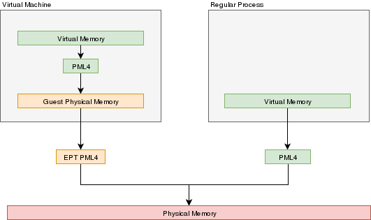
Memory
In a VMX environment, there exists several layers of memory:
- Guest virtual memory: The guest's virtual memory if paging is enabled in the Guest. That memory translates
to guest physical memory using the guest's paging structures, entirely controlled by the guest.
- Guest physical memory: This is the physical memory from the VM's point of view. From the hypervisor's point
of view, this is just virtual memory that has to be mapped to physical memory. This memory would be
allocated lazily as the VM uses more and more memory. This memory is mapped to physical memory
by the hypervisor.
- Physical memory: This is the real hardware physical memory as seen by the host's CPU.
For more details about how paging works, please refer to Memory Paging
For the VM to have memory, some of the host's physical memory must be assigned to the VM. The guest's physical memory is seen as
virtual memory by the host. To assign memory to the guest, a feature provided by the CPU called "EPT" can be used. EPT works
Just like the regular paging system. It is a way to map guest-physical addresses to real physical addresses using a paging
structure with a PML4 table on top.
So a guest would prepare it's own internal paging system and have it's own PML4 table. When an a virtual address inside the VM
needs to be resolved, it will be resolved to the guest's physical address using its PML4 table. Then, the guest-physical address
will be resolved using the EPT's PML4 table. So 2 translations would be done.
EPT is enabled by setting the "Enable EPT" bit in the VM-Execution controls. When enabled, an EPT PML4 structure
must be prepared and and the base address of that structure must be stored in the VMCS EPT pointer
Lazy allocation of guest physical memory
When a guest is launched with, for example, 16gb of ram, it would not be desirable to reserve that entire
memory on the hypervisor immediately. Instead, it would be preferable to allocate that memory in a lazy allocation
fashion. A guest might never use it's entire RAM so reserving it on the hypervisor would be a waste.
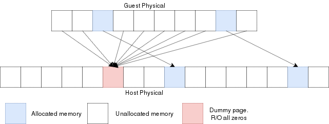
Reading an unallocated guest physical page will return zeros. Writing to it will trigger a EPT violation. The VMM can then reserve
a physical page and map it there instead of the dummy page.
When the guest is launched, a single page of write-protected physical memory (filled with zeros) should be mapped to all the guest
physical memory. If the VM's BIOS starts probing memory by reading all of it, every 4k would be mapped to that single page so the BIOS would read zeros and think it is
reading valid memory. If the BIOS (or the guest OS) writes into
memory, a VMexit would occur because writing to any address would map to this write-protected physical page.
The hypervisor can then allocate a new R/W page to the EPT's paging structure for the guest physical memory. Of
course, if the guest does a write/read-back kind of algorithm the probe the memory, then all the guest physical
memory will have been allocated because all pages will have been written to, so all bets are off.
Reclaiming freed-up memory is a different story. The only way the hypervisor can
know about memory that can be reclaimed is by using memory balooning. The virtio
specification describes a memory baloon device that can be implemented for that
purpose.
When the guest will access guest-physical memory that is unmapped to physical memory, a VMExit will occur.
The hypervisor needs to evaluate if the guest-physical address falls into the possible addressing space of the VM
(i.e. if it is trying to access memory beyond the last byte of the virtual RAM). If the memory is unmapped
because of the lazy-loading scheme, then a new page can be allocated. If it is because that memory address should
not be mapped, then an exception will be injected back in the VM and the guest will need to handle that.
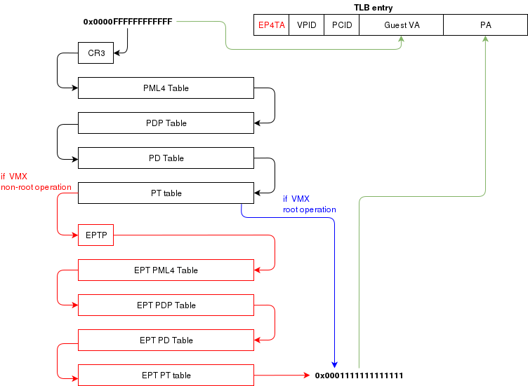
Translation Lookaside Buffer (TLB)
When the process translate a virtual address to a physical address, the translation is cached in the TLB so that
it wont have to walk through the page tables again next time. In a virtual environment, the CPU only has one TLB
in which is caches translations for:
- All host virtual/physical mappings
- All guest-physical/physical mappings (of all VMs)
- All guest-virtual/guest-physical mappings (of all VMs).
This could create collisions in the TLB. For example, 2 VMs could have a mapping of virtual address 0x00000000. A simpler
case would be two processes with different virtual memory mappings running on the host. For this reason, as I described in
another article (Process Context ID and the TLB), the TLB supports processID-tagging. With VMX, two new taggings exist: VPID and EP4TA.
VPID is the tagging of a TLB entry for a specific virtual CPU. This is only tru if VPID is enabled in the VMCS and if a non-zero
VPID has been set in the VMCS. In such a case, every guest-virtual to guest physical translations that are inserted in the TLB
will be tagged with the current VPID. This means that another VCPU can insert a similar entry in the TLB and it will be tagged
with a different VPID. When the MMU looks up a mapping in the TLB, it will only consider those tagged with the current VPID.
EP4TA tagging is done when EPT is enabled. Every guest-virtual to host-physical (going through EPT tables) are cached in the TLB
with a tagging of the current EPT,PCID and VPID. The EPT ID (EP4TA) is derived from the current EPTP, so there is no specific
ID to set, unlike PCID and VPID.
If VPID is not enabled, then the VPID tag is always 0 and is always ignored during lookups. A lookup while EPT
is active (during non-root operation) will only consider entries with a matching EP4TA.
I'm a bit confused by what the Intel documentation says about EPT and the TLB. From what I can understand,
it seems like the TLB will cache guest-virtual mappings to host-physical addresses. Those are called "combined mappings"
When EPT is enabled, these entries will be tagged with the current EP4TA,VPID,PCID.
If VPID is not enabled:
- entries will be tagged with VPID=0.
- On vmexit/vmentry, all entries with VPID==0 will be invalidated, regardless of EP4TA tag.
For this reason, I am enabling VPID with a tag of "1" for all my VCPUs. The documentation clearly states that having the same VPID
for different EPT is acceptable.
When the guest will invoke "invlpg" or "invpcid", these instructions should be trapped because they will invalidate all
requested TLB entries regardless of the current EP4TA. So the VMM should set a VMExit on those operations and emulate them
using "invept. That's what I am understanding from section 28.3.3.1, but section 28.3.3.3 says that when EPT is enabled, there is
no need to emulate these instruction.
When to invalidate
When a VMExit occurs because of an EPT violation, the faulting page will always be invalidated in the TLB. In my OS,
I use the EPT violation handler to allocate more memory to the VM. When the VM resumes, the TLB will be up to date the VM
will be writing data in the correct physical page. If the VM is rescheduled on another core where the stale TLB entry exists
for that address, then it will be accessing the wrong physical page. The TLB was only invalidated on the CPU that detected
the EPT violation. For this reason, the host needs to do a TLB shootdown on all host CPUs. This done by sending a IPI to
all other CPUS. The CPUS will then execute "invept" to invalidate TLB entries associated with the EPT in question.
The "invept" can be used to invalidate ALL tlb entries tagged with a specific EPT, or all EPT.
Initialization
The initialization of vmx mode is well described. There are a couple of web sites with examples that can be found using a simple
google search. But the Intel SDM #3 describes an algorithm to do so. Basically, this is what needs to happen:
- detect support for VMX
- create a VMCS for vmxon
- execute vmxon
- create a VMCS for a VM and write all required data in it
- run vmlaunch
It's important to note that VMXON should be executed on all CPUs and this should be done when the hypervisor starts.
In my OS, I do this as soon as I switch to long mode on all cores and I leave it on all the time.
The tricky part is to get the VMCS for the guest initialized correctly. I had to spend quite some time
fine-tunning the fields. If VMLAUNCH fails, the zero flag will be set, then you can do a VMREAD to VM_INSTRUCTION_ERROR
to get the error code. Then, the SDM (chapter 26) describes all the checkings that the CPU does so you can
walk through those and make sure your code is compliant.
Also, it seems like access rights and segment limits for guest segment descriptors still need to be properly set even if
the VM will run in real mode. If I recall correctly, it's because they will be checked even in real mode and
that is how "unreal mode" works.
I am not going in the details about this because everyone talks about that and the SDM has very good documentation
about it.
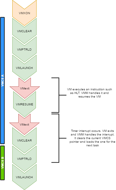
Multi-tasking (in a multi-core environment)
Running a VM in a multitasking environment requires a bit of logic that is beyond that the Intel manuals describe. This is because
a VM really is just a process getting a time slice with the scheduler. So when the process is scheduled out, the entire VM is paused.
Every VCPU is managed by one and only one thread in the OS. So each thread has a VMCS (if it is running a VCPU)
Before the task get's scheduled out, vmclear is executed so that any cached data gets flushed in the VMCS.
At least that's what Intel recommends to do. When a task is scheduled back in, VMPTRLD is executed to load the VMCS (if any) that
this task manages.
When a timer interrupt occurs and it's time to do a context switch on the host, since the VM runs as part of
a process on the host, it is normal that it gets interrupted and that time is given to another process.
That process might want to run a VM also, or maybe it's just a normal application. When the timer interrupt occurs,
this will trigger a VMExit and the CPU will be back at executing code in the context of the host. The thread will change.
When getting back to this thread, we will do a VMRESUME to continue executing the VM. We will also reload the VMCS
with VMPTRLD because another process might have loaded another VMCS. We could even be running on another processor
in a multi-core system. And remember, loading a VMCS is only loaded on the current core. So with 4 cores,
you could have 4 different VMs running
When the VMM is running in root-operations because of a VMexit, it could have been scheduled out at any moment before doing the
VMRESUME. So when VMRESUME is executed, it is possible that VMCLEAR was executed before because of a task switch. For this
reason, the OS checks if VMRESUME fails and executes VMLAUNCH instead.
The OS should avoid scheduling VCPUs from cores to cores because moving a VCPU to another core makes it mandatory to do a VMCLEAR.
My OS does not make such effort and blindly does a VMCLEAR on every task switch. So performance could be improved there.
And interesting point here is that after executing VMLAUNCH, control never returns to the calling function (unless vmlaunch fails).
VMLAUNCH and VMRESUME will jump in the guest's code without pushing a return address. A VMExit handler has been defined in the VMCS,
so from the host's point of view. control skips from vmlaunch to the handler. Also, since the stack is setup in the host's section
of the VMCS, the VMM gets a brand new stack everytime the VMExit handler gets called. This means that there is no need to pop the
stack before executing VMLAUNCH/VMRESUME
VM Exits
When the cpu is running in non-root operation (running VM code), it's pretty much as if the VM
was running bare-metal. But Several events can make the VM exit back to root-operation (the hypervisor).
A VM exit will restore the CPU state back to what it was set in the VMCS before vmlaunch. The hypervisor
must determine what caused the VMExit and take proper action. VMExits are similar to interrupts because
the general purpose registers are not automatically saved. A VMExit handler must save the registers and
restore them before resuming the VM otherwise the VM will be corrupted. As per the host section of the
VMCS though, a separate stack is being set. The VMM could alter the VM state by changing data in the
VMCS before resuming the VM. For example, if the VMExit occured because of an exception of type #UD,
the VMM could emulate the invalid instruction and change general purpose registers and flags in the VM.
Interrupts
When an interrupt needs to be delivered to the host, a VMExit will occur and control will be immediately
given to the VMM's exit handler. At that moment interrupts will be disabled (flags.IF=0).
When bit 15 (Acknowledge interrupt on exit) is cleared on the VM Exit control, the interrupt is not acknowleged by the processor. This means that as soon as the "IF" flag becomes 1 (ie, when executing "sti"),
the interrupt handler will get called.
In my hypervisor, if such a VM exit is detected, the kernel executes "sti" and finally
"vmresume". This will let the host execute the handler as soon as interrupts are re-enabled, then
control will be handed back to the VMM exit handler to execute "vmresume"
It is worth noting that it doesn't seem to matter if interrupts were cleared before VMLAUNCH.
Interrupts will still trigger a VMExit and the interrupt will be pending until the VMM enables them (using "sti")
Multiple VCPU
supporting multiple VCPUs for a VM requires having 1 VMCS per VCPU (just as if they were all used in independent VMs).
But the hypervisor has to make those CPUs dormant until a "Startup IPI" is sent. From there, the hypervisor can configure
the VCPU to start executing code at the desired address. But the main thing here is that only one VCPU would be started
when the VM is launched. My OS does not yet support this. I am focussing on 1 VCPU for now
One thing to consider when running multiple VCPUs is that one of them could trigger a VMExit because of a memory
allocation requirement (as described in a previous section of this article). In such a case, another VCPU could be running,
or the current thread could get scheduled out with another VCPU one being scheduled in. So extra care
should be taken to ensure that memory does not get corrupted.
Other thoughts
There are many other things to consider to improve performances and to make the design robust
Things to consider are:
- Trapping "hlt" with a vmexit so we can schedule out an idle VCPU
- Trapping TLB/MMU operations to better manage memory
- Trapping IO operations so that the hypervisor can retain control over hardware.
- Setup a virtual apic so that VCPUs can receive interrupts (and make a scheduler).
The code
For reference, this is a part of my VMX code:
What next?
There is still some work to be done for implementing a full hypervisor. The work done here only creates
virtual CPUs. The hypervisor needs to emulate other hardware such as a hard drive, a network card, a video card, keyboard etc.
I would probably write virtio devices since they are easy to code and very efficient.
Another big part that is missing is a BIOS. The hypervisor has to provide a BIOS for your guests since they rely on that to boot.